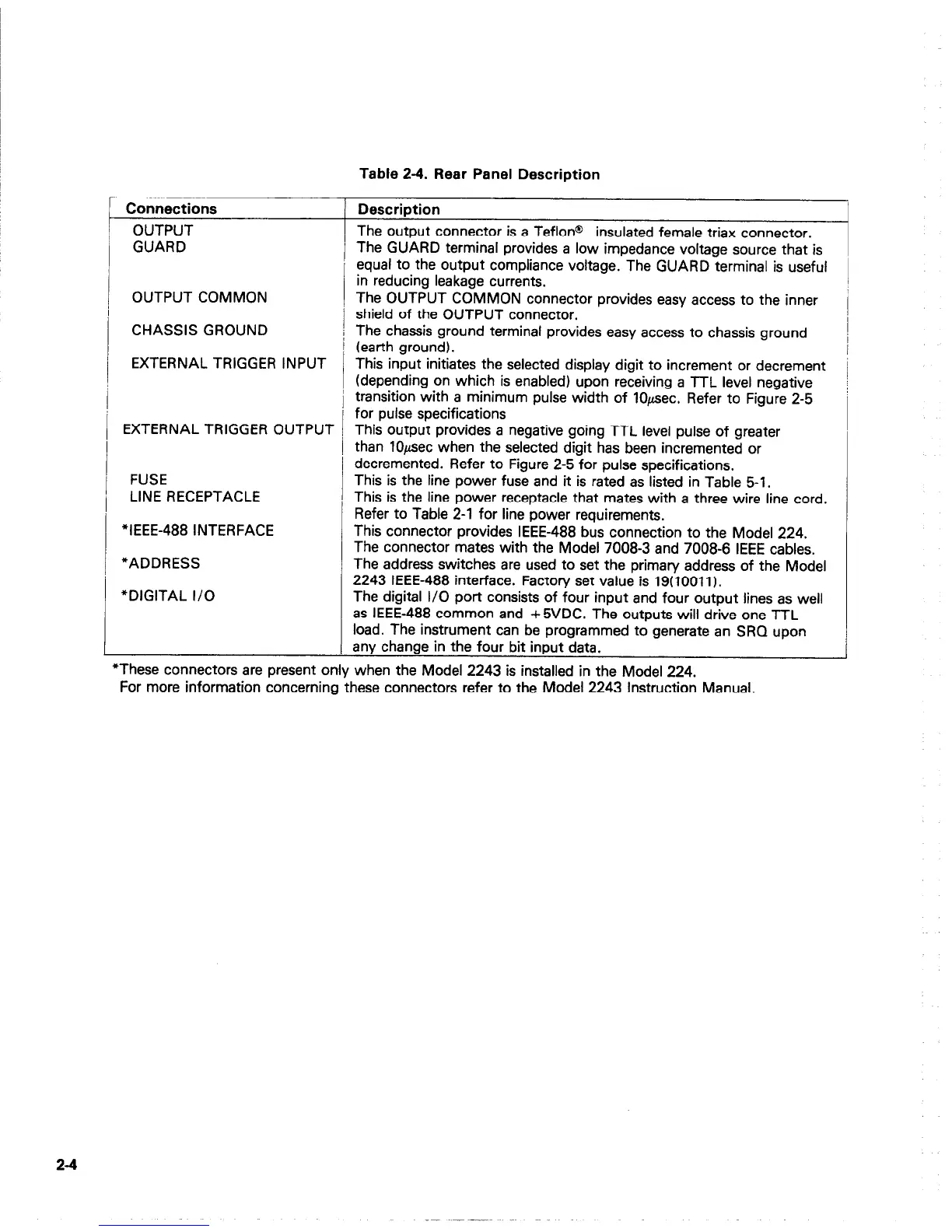
Table 2-4. Rear Panel Description
Connections
Description
OUTPUT
The output connector is a Teflon@
insulated female triax connector.
GUARD
The GUARD terminal provides a low impedance voltage source that is
equal to the output compliance voltage. The GUARD terminal is useful
in reducing leakage currents.
OUTPUT COMMON The OUTPUT COMMON connector provides easy access to the inner
shield of the OUTPUT connector.
CHASSIS GROUND
/ The chassis ground terminal provides easy access to chassis ground
I (earth ground).
EXTERNAL TRIGGER INPUT This input initiates the selected display digit to increment or decrement
(depending on which is enabled) upon receiving a TTL level negative
i transition with a minimum pulse width of lO@ec. Refer to Figure 2-5
for pulse specifications
EXTERNAL TRIGGER OUTPUT This output provides a negative going TTL level pulse of greater
! than lO@ec when the selected digit has been incremented or
decremented. Refer to Figure 2-5 for pulse specifications.
FUSE
This is the line power fuse and it is rated as listed in Table 5-l.
LINE RECEPTACLE This is the line power receptacle that mates with a three wire line cord.
Refer to Table 2-l for line power requirements.
“IEEE-488 INTERFACE This connector provides IEEE-488 bus connection to the Model 224.
The connector mates with the Model 7008-3 and 7008-6 IEEE cables.
*ADDRESS The address switches are used to set the primary address of the Model
2243 IEEE-488 interface. Factory set value is 19(10011 I.
*DIGITAL I/O The digital I/O port consists of four input and four output lines as well
as IEEE-488 common and +5VDC. The outputs will drive one TTL
load. The instrument can be programmed to generate an SRQ upon
any change in the four bit input data.
*These connectors are present only when the Model 2243 is installed in the Model 224.
For more information concerning these connectors refer to the Model 2243 Instruction Manual.
2-4