2
5
6
-
R372
R370
R36d
R347
,
ISK
R33>
39
R340
:
-
KX)6
P/J1009
JiOl3
I =uuut
E37E
4 33K
-1.-
R337
+5v-
R33E
f5V
NC
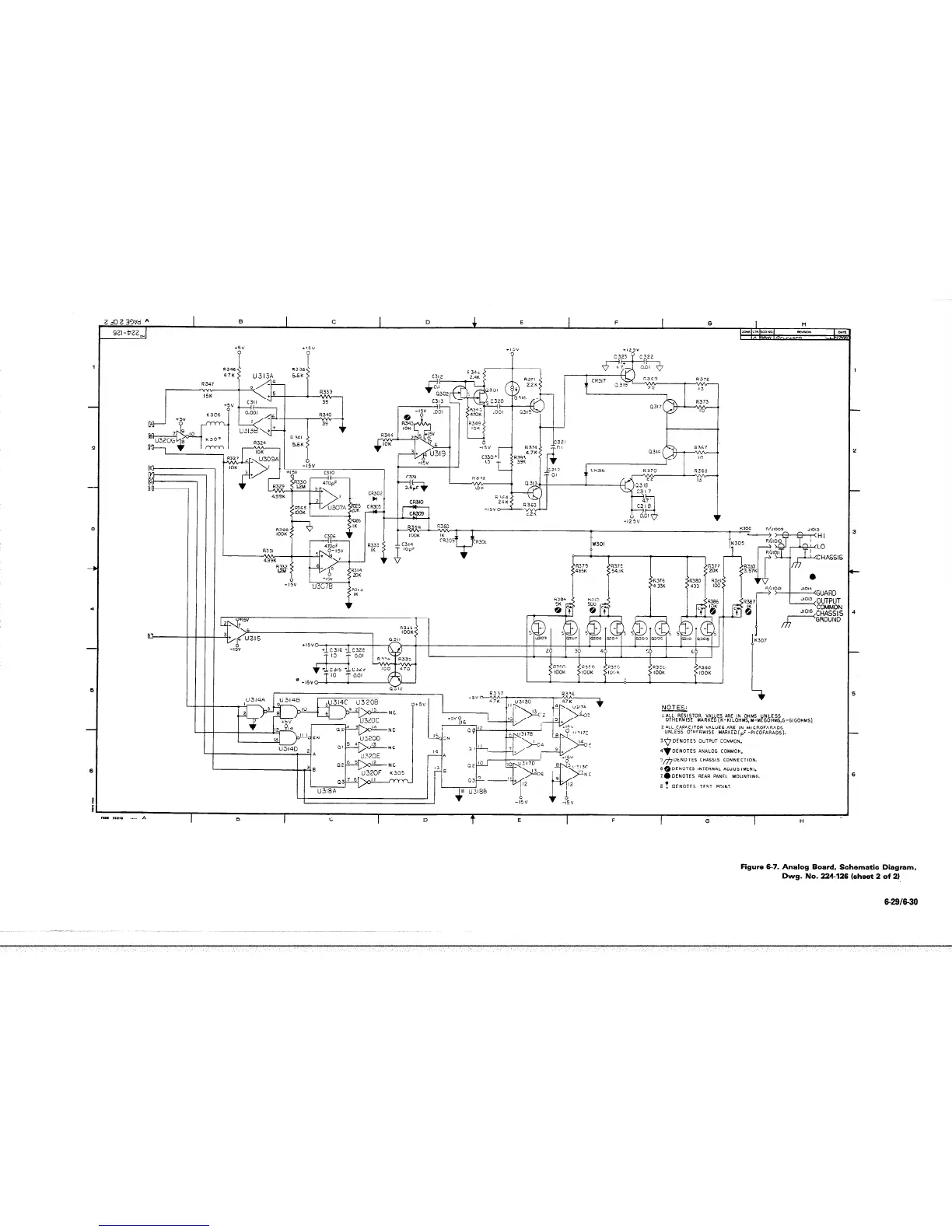
NOTES:
+5v?,F
I.ALL RESISTOR VALUES ARE IN OHMS UNLESS
OTHERWISE MARKED(K-KILOHMS,H-MEGOHMS,G-GIGOHMS)
U32OD
EN
2.ALL CAPACITOR VALUES ARE IN MICROFARADS
UNLESS OTHFRWISE MARKEDcpF -PICOFARAOS).
3.*
DENOTES OUTPUT COMMON.
4q DENOTES ANALOG COMMON.
‘h
DENOTES CHASSIS CONNECTION.
~~DENOTES INTERNAL ADJUSTMENT.
Z.DENOTES REAR PANEL MOUNTING.
62 DENOTES TEST POINT.
3
: -8
U32OF
K305
U318.4
Figure 6-7. Analog Board, Schematic Diagram,
Dwg. No. 224-126 (sheet 2 of 2)
6-2916-30

 Loading...


