SPECIFICATIONS
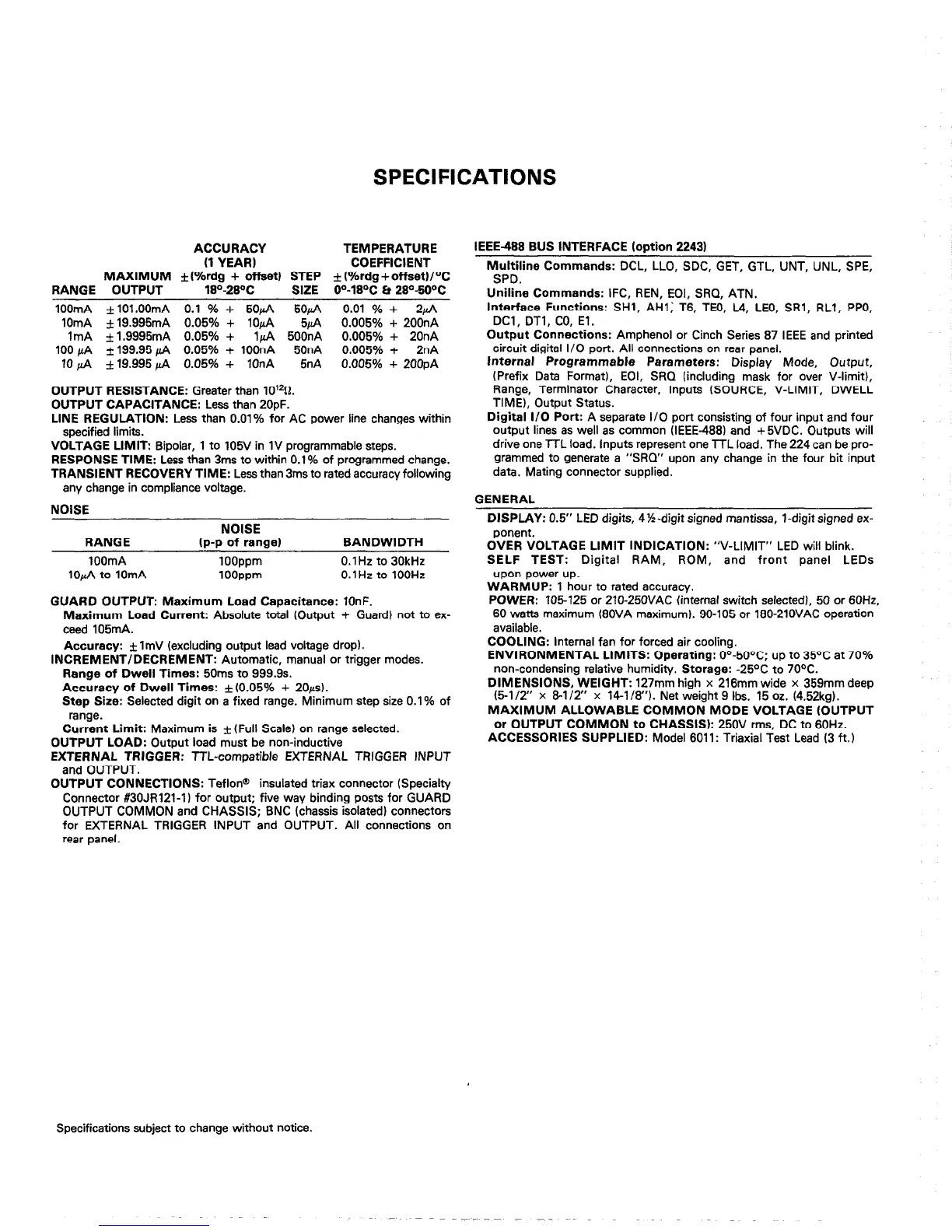
ACCURACY
(1 YEAR)
MAXIMUM +[%rdn + offset) STEP
TEMPERATURE
COEFFICIENT
f (%rda + offset)/OC
RANGE OUTPUT - 18z-280C SIZE ii=‘-18°C Et 28O-50°C
IOOmA f101.00mA 0.1 % + 5OuA
5OU.A
1OmA I19.995mA 0.05% + l&A $A
0.01 % + 2uA
0.005% + 20&A
ImA * 1.9995mA 0.05% + 1 pA 500nA 0.005% + 20nA
100 fi kl99.95 fi 0.05% + 100nA
50nA
0.005% + 2nA
IOfi kl9.995fi 0.05% + IOnA
5nA 0.005% + 20OpA
OUTPUT RESISTANCE: Greater than lO’*g.
OUTPUT CAPACITANCE: Less than 2OpF.
LINE REGULATION: Less than 0.01% for AC power line changes within
specified limits.
VOLTAGE LIMIT: Bipolar, 1 to 105V in 1V programmable steps.
RESPONSE TIME: Less than 3ms to within 0.1% of programmed change.
TRANSIENT RECOVERY TIME: Less than 3ms to rated accuracy following
any change in compliance voltage.
NOISE
RANGE
IOOmA
IOfi to IOmA
NOISE
(p-p of range)
IOOppm
IOOppm
BANDWIDTH
0.1 Hz to 30kHz
O.lHz to 1OOHz
GUARD OUTPUT: Maximum Load Capacitance: 10nF.
Maximum Load Current: Absolute total (Output + Guard) not to ex-
ceed 105mA.
Accuracy: * ImV (excluding output lead voltage drop).
INCREMENT/DECREMENT: Automatic, manual or trigger modes.
Range of Dwell Times: 50ms to 999.9s.
Accuracy of Dwell Times: f (0.05% + 20~s).
Step Size: Selected digit on a fixed range. Minimum step size 0.1% of
range.
Current Limit: Maximum is f (Full Scale) on range selected.
OUTPUT LOAD: Output load must be non-inductive
EXTERNAL TRIGGER: TTL-compatible EXTERNAL TRIGGER INPUT
and OUTPUT.
OUTPUT CONNECTIONS: Teflon@
insulated triax connector (Specialty
Connector #30JRl21-I) for output; five way binding posts for GUARD
OUTPUT COMMON and CHASSIS; BNC (chassis isolated) connectors
for EXTERNAL TRIGGER INPUT and OUTPUT. All connections on
rear panel.
IEEE-488 BUS INTERFACE (ootion 22431
Multiline Commands: DCL, LLO, SDC, GET, GTL, UNT, UNL, SPE,
SPD.
Uniline Commands: IFC, REN, EOI, SRQ, ATN.
Interface Functions: SHl, AHI: T6, TEO, L4, LEO, SRl, RLI, PPO,
DCI, DTl, CO, El.
Output Connections: Amphenol or Cinch Series 87 IEEE and printed
circuit digital I/O port. All connections on rear panel.
Jnternal Programmable Parameters: Display Mode, Output,
(Prefix Data Format), EOI, SRQ (including mask for over V-limit),
Range, Terminator Character, Inputs (SOURCE, V-LIMIT, DWELL
TIME), Output Status.
Digital I/O Port: A separate I/O port consisting of four input and four
output lines as well as common (IEEE-4881 and +SVDC. Outputs will
drive one ‘ITL load. Inputs represent one TTL load. The 224 can be pro-
grammed to generate a “SRQ” upon any change in the four bit input
data. Mating connector supplied.
GENERAL
DISPLAY: 0.5” LED digits, 4%-digit signed mantissa, l-digit signed ex-
ponent.
OVER VOLTAGE LIMIT INDICATION: “V-LIMIT” LED will blink.
SELF TEST: Digital RAM,
ROM, and front panel LEDs
upon power up.
WARMUP: 1 hour to rated accuracy.
POWER: 105125 or 210-250VAC (internal switch selected), 50 or 60H2,
60 watts maximum (80VA maximum). 90-105 or 180-210VAC operation
available.
COOLING: Internal fan for forced air cooling.
ENVIRONMENTAL LIMITS: Operating: O”-50°C; up to 35OC at 70%
non-condensing relative humidity. Storage: -25OC to 70°C.
DIMENSIONS, WEIGHT: 127mm high x 216mm wide x 359mm deep
(5-l/2” x &l/2” x 14-l/8”). Net weight 9 Ibs. 15 oz. (4.52kg).
MAXIMUM ALLOWABLE COMMON MODE VOLTAGE (OUTPUT
or OUTPUT COMMON to CHASSIS): 250V rms, DC to 60Hz.
ACCESSORIES SUPPLIED: Model 6011: Triaxial Test Lead (3 ft,)
Specifications subject to change without notice.