2260B Series User Manual
112
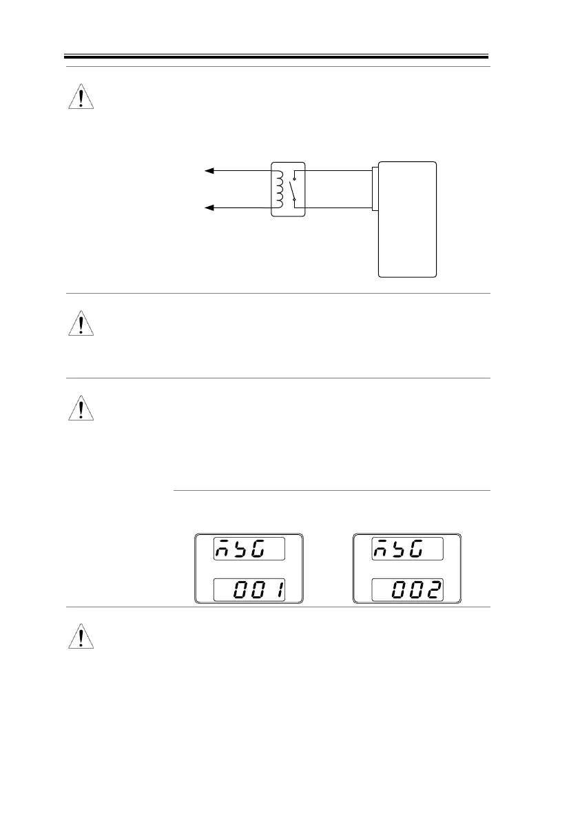
When using a switch over long distances, please
use a switch relay to extend the line from the coil
side of the relay.
Switch
Relay
Line
extention
Analog
connector
Output
Terminal
24
2
If a single switch control is to be used for multiple
units, please isolate each instrument. This can be
achieved by using a relay.
Ensure the cables used and the switch exceed the
isolation voltage of the power supply. For example:
insulation tubes with a withstand voltage higher
than the power supply can be used.
Messages: If F-94 = 0 (High = on) and the pin 24 is
low (0) “MSG 001” will be displayed on the display.
If F-94 = 1 (Low = on) and the pin 24 is high (1)
“MSG 002” will be displayed on the display.
Output ON/OFF Delay Time (F-01, F-02) are
disabled when the output is set to external control.
See the normal function settings on 87 for details.

 Loading...


