List of Illustrations
1 Getting Started
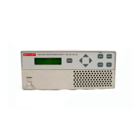
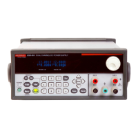
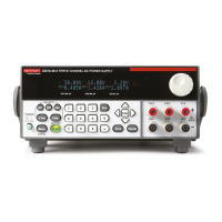
Figure 1-1 Model 2306 and 2306-PJ dual channel battery/charger simulator ..................... 1-4
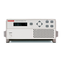
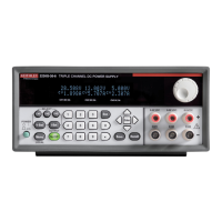
Figure 1-2 Model 2306-VS dual channel battery/char
ger simulator .................................... 1-5
Figure 1-3 Simplified power supply diagram ....................................................................... 1-6
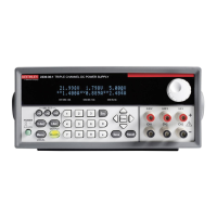
Figure 1-4 2304-DISP Remote display option (2306-DISP similar)
................................... 1-7
Figure 1-5 Fuse drawer location ........................................................................................... 1-9
2 Basic Power Supply Operation
Figure 2-1 Four-wire sense connections for battery and charger channels .......................... 2-3
Figure 2-2 Local sense connections ..................................................................................... 2-4
Figure 2-3 Sink operation ................................................................................................... 2-20
Figure 2-4 Preferred method .............................................................................................. 2-20
3 Pulse Current Measurements
Figure 3-1 Pulse current measurement ................................................................................. 3-2
Figure 3-2 Trigger delay for high pulse current meas
urement ............................................. 3-4
Figure 3-3 Determining voltage and c
urrent characteristics .............................................. 3-11
Figure 3-4 PCURent and SEARch time for pulse high measurement
................................ 3-18
Figure 3-5 Sample pulse forms for step method ................................................................
3-25
Figure 3-6 Sample one-shot only pulses for step method
.................................................. 3-25
Figure 3-7 Sample :STEP Pulse measurement ..
................................................................. 3-26
Figure 3-8 Pulse form with rise and fall steps ...
................................................................. 3-26
Figure 3-9 Pulse form with down steps first (600
μsec step duration) ................................ 3-27
4 Long Integration Measurements
Figure 4-1 Steady state for waveforms based on low pulse times ........................................ 4-3
Figure 4-2 Long integration, search, and reading time comparis
on ..................................... 4-5
Figure 4-3 TOUT and search time ...................................................................................... 4-16
5 Relay Control
Figure 5-1 External source relay control .............................................................................. 5-3
Figure 5-2 Internal source relay control ..................
............................................................. 5-3
Figure 5-3 Relay connector (9-pin D-sub) ..
......................................................................... 5-4
6 External Triggering (Model 2306-VS Only)
Figure 6-1 Typical trigger sequence ..................................................................................... 6-3
Figure 6-2 Model 2306-VS rear panel trigger connectors ..
.................................................. 6-3
Figure 6-3 Trigger input signal .............................................................................................
6-4
Figure 6-4 Trigger output signal ........................................................................................... 6-4
Test Equipment Depot - 800.517.8431 - 99 Washington Street Melrose, MA 02176
TestEquipmentDepot.com
 Loading...
