Getting Started 1-11
3. With the desired mode and active channel displayed, press ENTER. Now the display will
reflect this desired mode and active channel. Note that after selecting PULSE
CURRENT, use the
▲ or ▼ key to select the desired pulse measurement: pulse high,
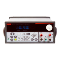
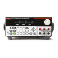
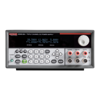
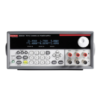
pulse low, or pulse average. Examples of the display modes are shown as follows:
Table 1-1
Display samples
Display mode
Samples for Channel #1
(Battery)
Samples for Channel #2
(Char
ger)
Reference
Actual V and I: 6.116 V #1 ON 6.116 V #2 ON Section 2
1.2058 A 1.2058 A
DVM input: DVM INPUT #1 OFF DVM INPUT #2 OFF Section 2
4.993 V 4.993 V
Pulse current: PULSE HI #1 ON PULSE HI #2 ON Section 3
2.1947 A 2.1947 A
PULSE LO #1 ON PULSE LO #2 ON
0.2147 A 0.2147 A
PULSE AVG #1 ON PULSE AVG #2 ON
1.1495 A 1.1495 A
Long integration: LONG INT #1 ON LONG INT #2 ON Section 4
1.0236 A 1.0236 A
NOTES “#1” o
r “#2” indicates present active channel. “ON” indicates that the output is turned
on. With the output turned off, “OFF” is displayed. See Section 2 for details on output-
ting current and voltage.
“NO
PULSE” is displayed if the output is OFF or pulses are not detected (output ON)
for pulse current and long integration display modes only.
When a change is made that affects the readings being taken, dashes are displayed
inste
ad of readings. The dashes remain until a valid reading for the new condition is
taken.
Default settings
The power supply can be set to power-on with the factory default conditions (RST defaults)
or to user-saved setup conditions. The factory default conditions are listed in Table 1-2.
Test Equipment Depot - 800.517.8431 - 99 Washington Street Melrose, MA 02176
TestEquipmentDepot.com
 Loading...
