SECTION2
Operation
2.22.3 Output Triggers
The Source Measure Unit can be programmed to
output
one
or
more trigger pulses at various strategic times dur-
ing operation. When an
output
trigger occurs, a negative-
going
TIL
level pulse (see Figure
2-53)
is applied to the
TRIGGER OUT connector (see Figure
2-52)
on the rear
panel.
An
output
trigger is used to cause
an
external in-
strument to perform one
or
more operations. Paragraph
2.25
shows
how
external triggers are used to control a test
system that uses two
or
more Source Measure Units.
Trigger
Out
In
00
Trigger
Common
Conected
to
Chassis
A.
Trigger
Connections
<("~"
Low
(Common)
BNC
B.
Trigger
In
and
Out
Connector
Configuration
Figure
2-52.
Trigger
In
and
Trigger
Out
Connections
Output
triggers are listed
and
explained
in
Table
2-14.
Notice that for all except the pulse
end
and
sweep
end
output triggers, one, two
or
three
output
triggers occur
during each SDM cycle of operation. The pointer(") indi-
cates when the triggers occur
in
each SDM cycle. For ex-
ample:
For this selection, an
output
trigger occurs after the
source phase
and
delay phase of every SDM cycle of op-
eration.
2-88
+
+
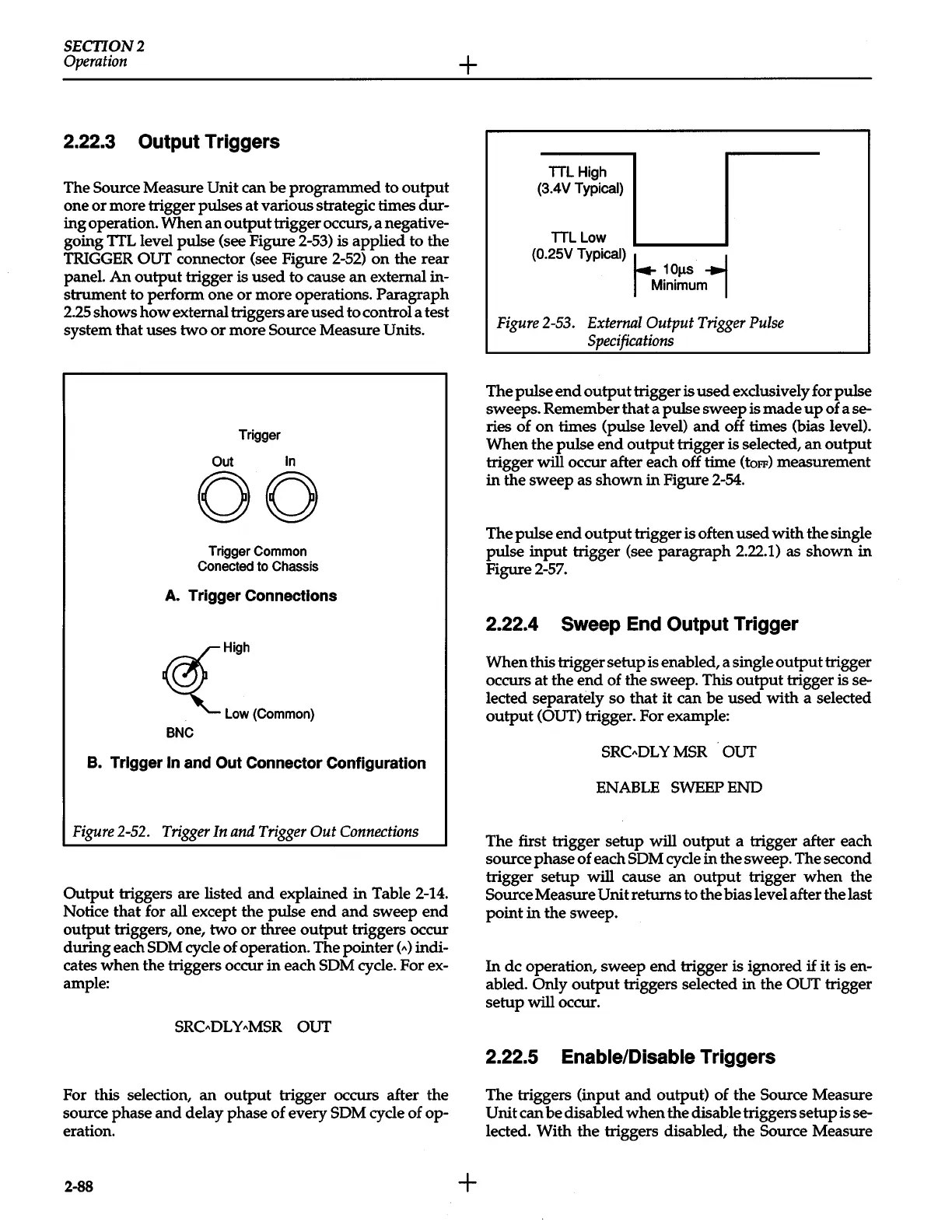
TTL
High
(3.4V
Typical)
TTL
Low
(0.25V Typical) h
~
1
OJ.LS
Minimum
Figure
2-53.
External
Output
Trigger
Pulse
Specifications
The pulse
end
output
trigger is used exclusively for pulse
sweeps. Remember that a pulse sweep is made
up
of a se-
ries of
on
times (pulse level)
and
off times (bias level).
When the pulse
end
output
trigger is selected,
an
output
trigger
will occur after each off time
(toFF)
measurement
in the sweep as shown
in
Figure
2-54.
The pulse end
output
trigger is often used with the single
pulse
input
trigger (see paragraph 2.22.1) as shown in
Figure
2-57.
2.22.4 Sweep
End
Output Trigger
When this trigger setup is enabled, a single
output
trigger
occurs at the
end
of the sweep. This output trigger is se-
lected separately so that it can be used with a selected
output
(OUT) trigger. For example:
SRC"DLY
MSR OUT
ENABLE SWEEP END
The first trigger setup
will
output
a trigger after each
source phase
of
each SDM cycle in the sweep. The second
trigger setup
will cause
an
output
trigger
when
the
Source Measure Unit returns to the bias level after the last
point
in
the sweep.
In
de operation, sweep end trigger is ignored
if
it is en-
abled. Only
output
triggers selected
in
the OUT trigger
setup
will occur.
2.22.5 Enable/Disable Triggers
The triggers (input
and
output) of the Source Measure
Unit can be disabled
when
the disable triggers setup is se-
lected. With the triggers disabled, the Source Measure
 Loading...


