+
SECT10N2
Operation
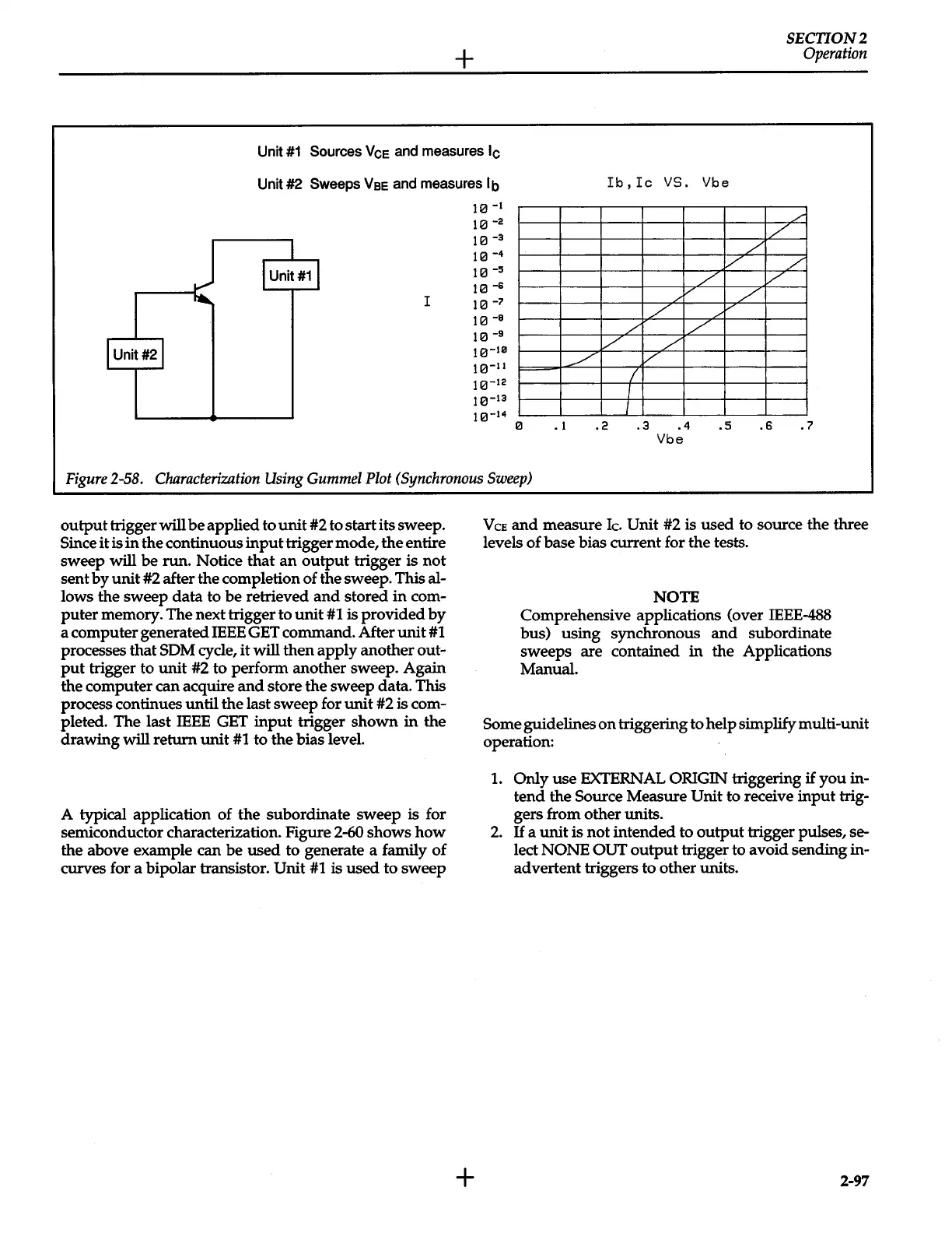
Unit
#1
Sources
Vee
and
measures
lc
Unit #2
Sweeps
Vee
and measures
lb
Ib,Ic
vs.
Vbe
tel
-I
./
11::1-2
/
11::1
-3
/
1111
-
4
v
/
I
Unit#11
HI-s
/
v
10
-s
v
L
....
I
112J
-7
/
10
-a
/
/
I
Unit#21
10
-s
v /
10-10
/
v
10-11
I
10-12
I
10-13
J
10-14
0
.I
.2
.3 .4
.5
.6
• 7
Vbe
Figure
2-58.
Characterization
Using
Gummel
Plot
(Synchronous
Sweep)
output
trigger
will
be
applied to
unit
#2
to
start
its sweep.
Since
it
is
in
the continuous
input
trigger mode,
the
entire
sweep
will
be run. Notice
that
an
output
trigger is
not
sent
by
unit
#2
after the completion
of
the sweep. This al-
lows the sweep
data
to
be
retrieved
and
stored
in
com-
puter
memory. The next trigger to
unit
#1
is
provided
by
a computer generated IEEE GET command. After
unit
#1
processes
that
SDM
cycle,
it
will
then
apply
another out-
put
trigger to
unit
#2
to perform another sweep. Again
the computer can acquire
and
store
the
sweep data. This
process continues until
the
last
sweep
for
unit
#2
is com-
pleted. The last
IEEE
GET
input
trigger
shown
in
the
drawing
will
return
unit
#1
to the bias level.
A typical application
of
the
subordinate
sweep
is for
semiconductor characterization. Figure
2-60
shows
how
the above example can be
used
to generate a family
of
curves for a bipolar transistor.
Unit
#1
is
used
to
sweep
+
VeE
and
measure
Ic.
Unit
#2
is
used
to source
the
three
levels
of
base bias current for
the
tests.
NOTE
Comprehensive applications (over IEEE-488
bus)
using
synchronous
and
subordinate
sweeps are contained
in
the
Applications
Manual.
Some
guidelines
on
triggering to help simplify multi-unit
operation:
1.
Only
use
EXTERNAL ORIGIN triggering
if
you
in-
tend
the
Source
Measure
Unit
to receive
input
trig-
gers from
other
units.
2.
H
a
unit
is
not
intended
to
output
trigger pulses, se-
lect NONE OUT
output
trigger to avoid sending in-
advertent triggers to other units.
2-97
 Loading...


