SECTION2
Operation
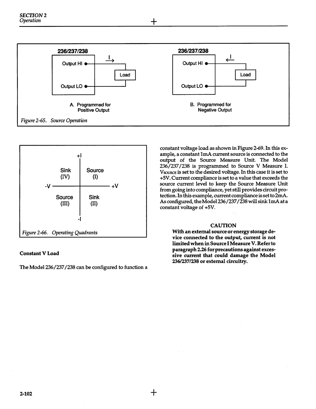
Figure
2-65.
236/237/238
Output
HI
-4
Output
LO-
A.
Programmed for
Positive
Output
Source
Operation
Sink
(IV)
+I
Source
(I)
I
-V
-----+----
+V
Source
(III)
-I
Sink
(II)
Figure
2-66.
Operating
Quadrants
Constant
V Load
1
Load
I
J
The Model
236/237/238
can
be
configured to function a
2-102
+
+
236/237/238
Output
HI
~
I
I
Load
I
Output
LO-
I
B.
Programmed for
Negative
Output
constant voltage load as shown
in
Figure 2-69.
In
this
ex-
ample, a constant
lmA
current source
is
connected to the
output
of the
Source Measure Unit.
The Model
236/237/238
is
programmed to
Source V Measure
I.
V
soURCE
is
set to the desired voltage.
In
this case
it
is set to
+5V.
Current compliance
is
set to a value that exceeds the
source current level to keep the
Source
Measure
Unit
from going into compliance,
yet
still provides circuit
pro-
tection.
In
this example, current compliance
is
set to 2mA.
As configured, theModel236/237
/238willsinklmAata
constant voltage of
+5V.
CAUTION
With
an
external source
or
energy storage de-
vice connected
to
the
output, current is
not
limited
when
in
Source
I Measure
V.
Refer to
paragraph
2.26
for precautions against exces-
sive current
that
could damage
the
Model
236/237/238
or
external circuitry.
 Loading...


