+
SECTION3
IEEE-488
Reference
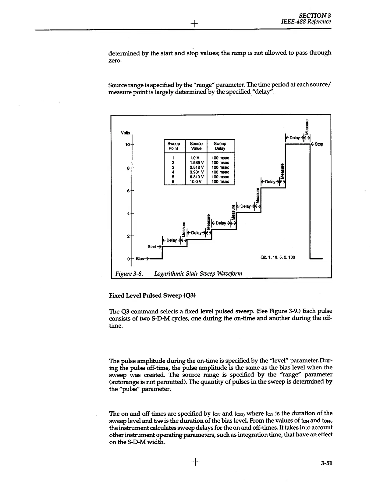
determined
by
the start
and
stop values; the ramp
is
not
allowed to pass through
zero.
Source
range is specified
by
the
"range"
parameter. The time period at each
source/
measure point
is
largely determined
by
the specified "delay".
2!
:::>
Volts
m
~Delay-f::E~
10
Sweep
Source
Sweep
Point
Value
Delay
~Stop
1
1.0V
100
msec
2
1.585V
100 msec
2!
8
3 2.512V
100msec
:::>
4
3.981
v
100msec
m
5
6.310V 100msec
~Delay+::E
6
10.0V
100
msec
6
2!
:a
.,
~~Delay+~
4
:8
2!
~~Delay4~
:a
::E
2
~~Delay"f1
~Delayf
1
Start~
0
Bias~
02.
1,
10, 5,
2,100
'--
Figure3-8.
Logarithmic
Stair
Sweep
Waveform
Fixed Level
Pulsed
Sweep
(Q3)
The Q3 command selects a fixed level pulsed sweep.
(See
Figure 3-9.) Each pulse
consists of two S-D-M cycles, one during the on-time
and
another during the off-
time.
The pulse amplitude during the on-time
is
specified
by
the '1evel" parameter.Dur-
ing the pulse off-time, the pulse amplitude is the same as the bias level when the
sweep was created. The source range
is
specified
by
the
"range"
parameter
(autorange is not permitted). The quantity of pulses
in
the sweep
is
determined
by
the
"pulse"
parameter.
The
on
and
off times are specified
by
toN
and
toFF,
where
toN
is
the duration of the
sweep level
and
toFF
is
the duration
of
the bias level. From the values of
toN
and
toFF,
the instrument calculates sweep delays for the
on
and
off-times.
It
takes into account
other instrument operating parameters, such as integration time, that have
an
effect
on
the S-0-M width.
+
3-51
 Loading...


