SECTION3
IEEE-488
Reference
+
U4-
Measurement Parameters
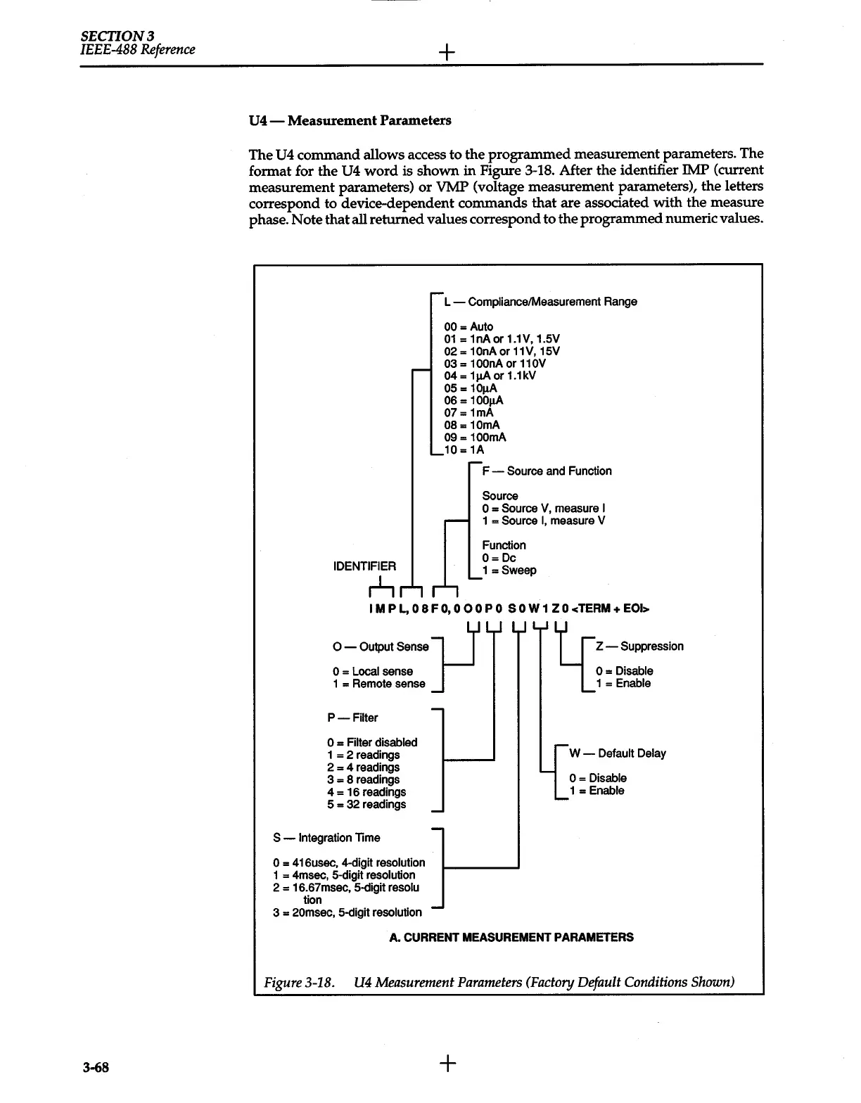
The
U4
command allows access to the programmed measurement parameters. The
format for the
U4
word
is shown
in
Figure
3-18.
After the identifier IMP (current
measurement parameters)
or
VMP (voltage measurement parameters), the letters
correspond to device-dependent commands that are associated with the measure
phase. Note that all returned values correspond to the programmed numeric values.
IDENTIFIER
r..L,
r-
L-
Compliance/Measurement Range
00
=Auto
01
=
1nA
or 1.1V, 1.5V
02
= 10nA
or
11V, 15V
03
=
100nA
or
110V
04
=
1J,LA
or 1.1kV
05
=
10J.LA
06
=
100J.LA
07
= 1mA
08
= 10mA
09 =
100mA
,
_
_10
=
1A
-
-
F-
Source
and Function
Source
0
=Source
V,
measure
I
1
= Source
I,
measure V
Function
O=Dc
_1
=Sweep
IMP
L,
08FO,O
00
PO
SOW1
ZO
<TERM+
EOI>
0-
Output Sense
J--1
0
=
Local
sense
1 = Remote sense
L
Z-
Suppression
0=
Disable
1
=Enable
P-Filter
0
=
Filter disabled
1
= 2 readings
2 = 4 readings
3 = 8 readings
4 = 16 readings
5 = 32 readings
S
- Integration
lime
0
= 416usec, 4-digit
resolution
1
= 4msec, 5-digit
resolution
2 = 16.67msec, 5-digit
resolu
tion
-
-
-
3 =
20msec,
5-digit
resolution -
r-.
W-
Default Delay
.......
0
=Disable
1
=Enable
A.
CURRENT
MEASUREMENT PARAMETERS
Figure
3-18.
U4
Measurement
Parameters
(Factory
Default
Conditions
Shown)
3-68
+
 Loading...


