+
APPENDIXF
236/237
Perfonnance
Verification
F.5.7
Low
Current
(1
nA
to
1
OmA)
Source
Ranges Verification
Set
up
the equipment as
shown
in
Figure F-7
and
per-
form the following steps to verify
the
lnA
to
lOrnA
source ranges:
1.
Use
Table F-8 to calculate
the
allowable readings for
the
lJ.IA
through
lOrnA
ranges. The values for
lo.9J.IA,
19J.IA,
190J.IA,
lo.9mA
and
19mA
were
previously calculated
and
recorded
in
Table
F-3.
After calculating the
al-
lowable readings, transfer
them
the
Table F-9.
2.
While
in
standby, configure the
Model236/237
to
source
OnA
on
the
lnA
source range
with
a compli-
ance limit
of
l.lV
on
the
l.lV
measurement range.
3.
While
in
standby, configure
the
Model263 to source
OnA
on
the
2nA range.
4.
With
ZERO
CHECK enabled, zero correct
the
Model
617
on
the
2pA
range.
5.
On
the
Model617, disable ZERO
CHECK
and
place
the
Model236/237
in
operate. Verify
that
the
read-
ing
on
the
Model617 is
within
the
limits specified
in
the
first
entry
of
Table F-9.
6.
Set
the
Model 617 to
the
20pA range,
and
set
the
Model236 to source
OnA
on
the lOnA range. Verify
that
the
reading
on
the
Model617 is
within
the
limits
specified
in
the
second
entry
of
Table F-9.
7.
Using
Table F-9 as a guide,
set
the Model236
/237
to
source zero
on
the
lOOnA
through
lOrnA
ranges
and
check
that
the subsequent readings are within the
listed limits.
8.
Place
the
Model 617
in
zero check
and
select the
20pArange.
9.
Place
the
Model236/237
in
standby
and
program
it
source -0.9nA
on
the
lnA
source range.
10.
While still
in
standby,
set
the
Model263
to source
+0.9nA
on
the 2nA range.
11. Place
both
the
Models 236/237
and
263
in
operate,
anddisableZEROCHECKon
theModel617. Verify
that
the
reading
on
the
Model617 is within the limits
specified
in
the
table.
12. Place
the
Model617
in
zero check,
and
the Models
263
and
236/237
in
standby.
13.
On
both
the
Models 263
and
236/237, reverse the po-
larity
of
the
sources.
That
is, set
the
Model236
/237
to
+0.9nA
and
the
Model263 to
-0.9nA.
14. Place
the
Models 236/237
and
263
in
operate,
and
disable zero check
on
the
Model617. Verify
that
the
reading
on
the
Model617
is still within the limits
specified
in
the
table.
15. Using
Table F-9 as a guide, repeat the basic proce-
dure
in
steps 8
through
14 to check the lOnA through
lOrnA
source ranges.
Note
that
for
the
lJ.IA
through
lOrnA
ranges,
the
source values for the Model
236/237
are
taken from Table F-3.
16.
Place
the
Model 617
in
zero check,
and
the Models
263
and
236/237
in
standby.
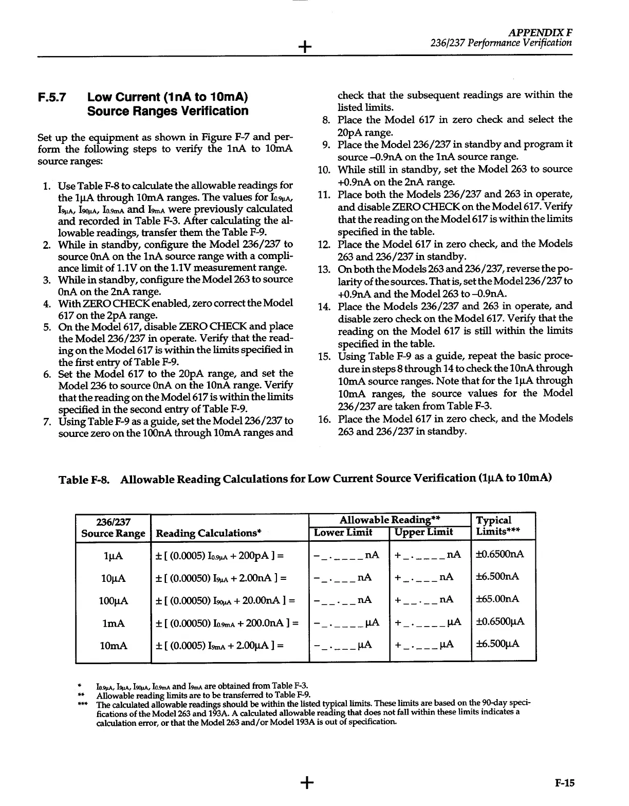
Table
F-8.
Allowable
Reading
Calculations
for
Low
Current
Source
Verification
(lJ.LA
to
lOrnA)
'136/'137
Source Range
Reading
Calculations*
lJ.IA
± [ (0.0005)
Io.9J.IA
+
200pA
]
=
lOJ.IA
± [ (0.00050)
19J,1A
+
2.00nA
]
=
lOOJ.IA
± [ (0.00050)
l90J,1A
+
20.00nA
]
=
lmA
± [ (0.00050)
lo.9mA
+
200.0nA
]
=
lOrnA
±
[
(0.0005)
I9mA
+
2.00J.IA
] =
*
Io.911A,
1911A,
I~,
Io.9mA
and
19mA
are obtained from Table
F-3.
**
Allowable reading
limits are to
be
transferred to Table
F-9.
Allowable
Reading**
Typical
Lower Limit
Upper
Limit
Limits***
-
nA
+
nA
±0.6500nA
-
----
-
----
-
nA
+
nA
±6.500nA
-
---
-
---
-
nA
+
nA
±65.00nA
--
--
--
--
-_.
____
J.IA
+
_.
____
J.IA
±0.6500J.IA
-_.
___
J.IA
+
_.
___
J.IA
±6.500J.IA
***
The calculated allowable readings should
be
within the listed typical limits. These limits are based
on
the 90-day speci-
fications
of
the Model263
and
193A. A calculated allowable reading that does
not
fall within these limits indicates a
calculation error,
or
that the Model263
and/
or
Model193A is
out
of specification.
+
F-15
 Loading...


