SECTION1
Getting
Started
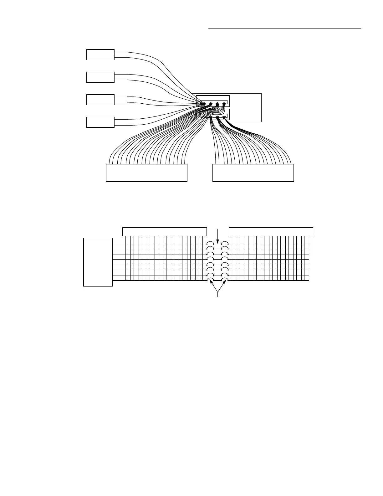
Figure
1-14.
Model236
Rear
Panel
1.7 REAR PANEL
FAMILIARIZATION
The
rear
panel
of
the
Model236
Source
Measure
Unit
is
shown
in
Figure 1-14.
G)
OUTPUTHI(GUARD)-OUTPUTHI(GUARD)
is a three-lug triax connector. OUTPUT
HI
is located
on
the
center conductor
and
GUARD is located
on
the
inner
shell.
0
SENSE
HI
(GUARD)-
SENSE
HI
(GUARD)
is a
three-lug triax connector.
SENSE
HI
is located
on
the
cen-
ter
conductor
and
GUARD
is located
on
the
inner
shell.
0
SENSE
LO
(OUTPUT LO)
-SENSE
LO (OUT-
PUT
LO)
is a three-lug triax connector.
SENSE
LO
is
lo-
cated
on
the
center
conductor
and
OUTPUT
LOis
located
on
the
inner
shell.
G)
OUTPUT
LO
-Five-way
binding
post
for OUT-
PUTLO.
0
CHASSIS
GROUND-
This
binding
post
is
con-
nected
to
chassis
ground.
For
optimum
shielding OUT-
PUT
LO
must
be
connected
to
this connector
(ground
link
installed).
Only
remove
the
ground
link
for floating
operation.
1-16
+
+
WARNING
Never
use
the
chassis
ground
binding
post
as
a
safety
earth
ground.
This
is
strictly a
"source-measure"
terminal
and
not
a
safety
terminaL
0
TRIGGER
OUT-
TRIGGER
OUT is a BNC
con-
nector. Provides negative
edge
TTL pulses. Referenced to
IEEE (chassis) common.
Can
be
used
to trigger
other
Source
Measure
Unit
operations.
0
TRIGGER
IN-
TRIGGER
IN
is a BNC connector.
Receives negative
edge
TTL level triggers. Referenced to
chassis common.
0
LINE
VOLTAGE-
Two-position slide switch. Set
to
available line
power
(115V
or
230V).
0
INTERLOCK-
Two
3-pin
male
connectors.
One
connects
to
the
test
fixture
and
the
other
can
be
connected
to
a
second
Source
Measure
Unit.
Cable connection to
the
Source
Measure
Unit
enables
the
interlock feature.
Used
to
place Source
Measure
Unit(s)
in
standby
when
lid
of
test fixture is
opened.
WARNING
When
using
the
INTERLOCK
feature
in
a
multiple
unit
test
system,
make
sure
all
the
 Loading...


