Output HI
1\
u
Guard
,--L--
OUT
1--r-
Output LO
A. Guarded
Output
Figure
2-3.
Guarded
Configurations
Guard
should always be
used
when
sourcing
or
measur-
ing
low current.
Guarded
connections
using
the Model
8006
test fixture are covered
in
paragraph
2.3.3.
Additional information explaining
the
effects
of
capaci-
tance
and
leakage current
on
Source
Measure
Unit
speed
and
accuracy is covered
in
Source Measure Considera-
tions.
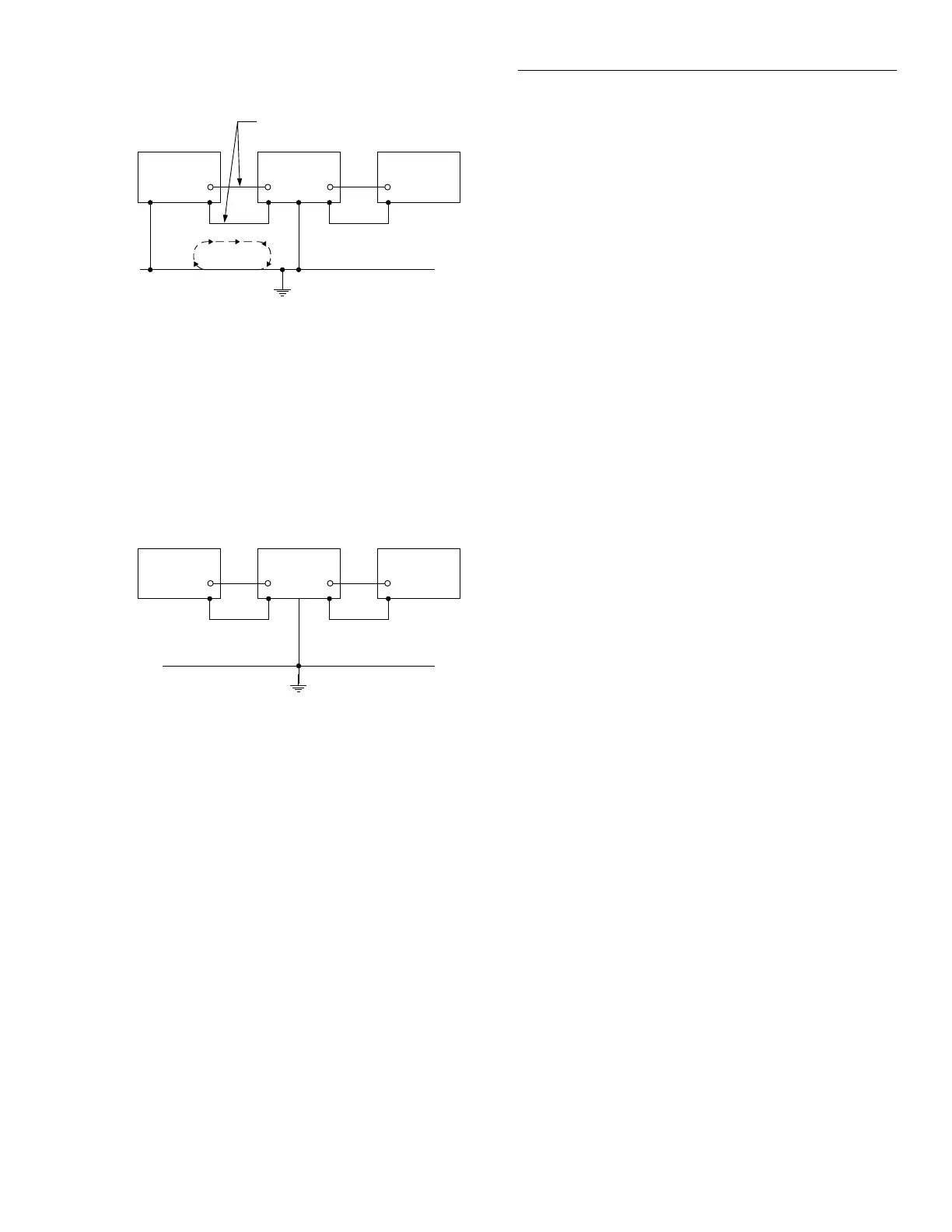
Shielding
Shielding for
the
DUT
must
be
provided. Without
proper
shielding,
surrounding
electric fields can induce noise
into the test circuit resulting
in
erratic
and
noisy measure-
ments.
Optimum
shielding is achieved only
when
the
OUTPUT
LO
to chassis
ground
link
on
the
rear
panel
is
installed. Unless
you
intend
to float
the
unit, always leave
the
ground
link
installed.
When properly connected to
the
Source Measure Unit,
the metal chassis
of
the
test fixture (such as
the
8006)
functions as a shield since
it
is connected to chassis
ground
via
the
outer
shields
of
the
triax cables. The
inner
panel
of
the test fixture, which is insulated from
the
chas-
sis, provides additional shielding
when
it
is connected to
circuit
low
or
the chassis.
In
most
cases, best results are
achieved
by
connecting
the
inner
panel
to circuit low.
However, trial
and
error
may
prove
that
connecting
the
inner
panel
to
the
chassis provides better shielding.
Figure 2-4 shows
the
basic shield configurations. Shield
connections using the Model
8006
are covered
in
para-
graph
2.3.3.
+
+
SECTION2
Operation
Output HI
(\
-u·
Guard
Sense HI
(\
Guard
I
J
r--'--
OUT
1.......;--
Sense LO
Output LO
B. Guarded
Output
and Guarded Sense
NOTE
The
inner
panel
of
the
test fixture
should
only
be
used
as a shield
when
guard
is
not
being
used.
When
using
guard,
the
inner
panel
should
be
connected to
the
OUTPUT
HI
guard
of
the
Source
Measure
Unit
(see para-
graph
2.3.3).
Sensing
Paragraph 2.10.3 explains
how
to select local
or
remote
sensing.
When
using
remote sensing, sense lines are ex-
tended
to the DUT. Figure 2-5 shows basic remote sens-
ing
configurations.
When
the
Source
Measure Unit
is connected to a test fix-
ture
(such as
the
Model8006),
external sense lines are ex-
tended
to
that
test fixture. Inside the test fixture, jumpers
can
be
used
to connect
the
external sense lines to
the
DUT
for remote sensing.
WARNING
With
remote
sensing
enabled,
an
open
sense
lead
will
result
in
lethal
voltages
appearing
at
OUTPUT
HI
and
GUARD.
This
voltage
can
cause
injury
or
death,
and
damage
exter-
nal
circuitry. Always
make
sure
that
the
sense
leads
are
properly
connected
before
enabling
remote
sense. NEVER
change
con-
nections
with
power
applied. Be
sure
to al-
ways
discharge
and/or
disconnect external
power
sources.
2-9
 Loading...


