SECTION2
Operation
Interlock
Switch
Mounting
The switch must
be
mounted inside the test box such
that it
will
be
closed
when
the lid of the test fixture is
closed. Opening the lid
must
cause the interlock switch
to open. There
must
never
be
enough clearance to allow
finger access inside the box while the switch is closed.
The interlock
must
be
designed so that it cannot
be
de-
feated.
Connecting
Interlock
Switch
to
Source
Measure
Unit
There are a few different methods that can
be
used to
connect the test fixture interlock switch
to
a
Source
Measure
Unit
and
are described as follows:
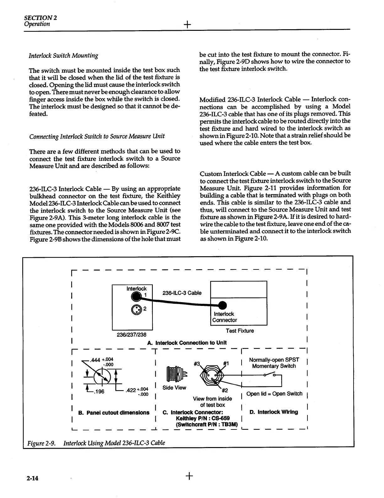
236-ILC-3 Interlock Cable -
By
using
an
appropriate
bulkhead connector
on
the test fixture, the Keithley
Model236-ILC-3 Interlock Cable can
be
used
to
connect
the interlock switch to the Source Measure Unit
(see
Figure 2-9A). This 3-meter long interlock cable is the
same one provided
with
the Models
8006
and
8007
test
fixtures. The connector needed is shown in Figure 2-9C.
Figure
2-9B
shows the dimensions of the hole that
must
+
be
cut into the test fixture to
mount
the connector.
Fi-
nally, Figure 2-9D shows
how
to wire the connector to
the test fixture interlock switch.
Modified 236-ILC-3 Interlock
Cable-
Interlock con-
nections can
be
accomplished
by
using a Model
236-ILC-3 cable that has one of its plugs removed. This
permits the interlock cable to
be
routed directly into the
test fixture
and
hard
wired to the interlock switch as
shown in Figure 2-10.
Note that a strain relief should
be
used
where the cable enters the test box.
Custom Interlock
Cable-
A custom cable can
be
built
to connect the test fixture interlock switch to the Source
Measure Unit. Figure
2-11
provides information for
building a cable that is terminated with plugs
on
both
ends. This cable is similar to the 236-ILC-3 cable and
thus,
will
connect to the Source Measure
Unit
and
test
fixture as shown
in
Figure 2-9A.
If
it is desired to hard-
wire the cable to the test fixture, leave one
end
of theca-
ble unterminated
and
connect
it
to the interlock switch
as shown
in
Figure
2-10.
r
-
- - - - - - - - - - - - - - - - - -
-~
236-ILC-3 Cable
236/237/238
Interlock
Connector
Test Fixture
I
,---
A.
Interlock
Connection
to
UnH
---,-------~--
----1
#3~1
Normally-open
SPST
1
1
B.
Panel
cutout dimensions
L.....--------1.
mmnltJlb
Momentary Switch
~
---o-'0~]
Side View
~
-------'
1
Open lid
=
Open
Switch
View from inside
of test box
C.
Interlock
Connector:
D.
Interlock Wiring
Keithley
PIN
: Cs-659
I I
(SWitchcraft
PIN
: TB3M)
-
- - -
-
-
·-
-
- -
-
-·
Figure
2-9.
Interlock
Using
Model236-ILC-3
Cable
2-14
+
 Loading...


