EasyManua.ls Logo

Keithley 7705 - Module Connections

Keithley 7705
10 pages
Print Icon
To Next Page IconTo Next Page
To Previous Page IconTo Previous Page
Loading...
Model 7705 Control Module Instructions for use with DAQ6510
077144900 / April 2018 3
Module connections
Do not attempt to perform this procedure unless qualified to do so. Failure to recognize and
observe normal safety precautions could result in personal injury or death.
Do not exceed the maximum specifications for the 7705 switching module. Refer to the
specifications provided in the data sheet. Failure to recognize and observe normal safety
precautions could result in personal injury or death.
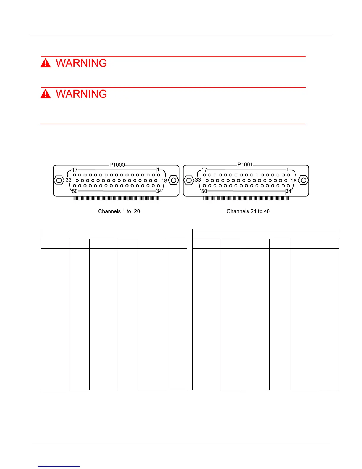
When looking at the rear connectors of the 7705 switching module, the connector on the left is P1000 and the
connector on the right is P1001, as shown in the following figure. Channel designations are shown in the
following table.
Figure 3: Model 7705 pinouts
Channel designations
P1000
P1001
CH
PIN
CH
PIN
PIN
CH
PIN
PIN
PIN
1 IN
6
8 IN
25
39
21 IN
6
25
39
1 OUT
8
8 OUT
26
40
21 OUT
8
26
40
2 IN
10
9 IN
27
41
22 IN
10
27
41
2 OUT
12
9 OUT
28
42
22 OUT
12
28
42
3 IN
14
10 IN
29
43
23 IN
14
29
43
3 OUT
16
10 OUT
30
44
23 OUT
16
30
44
4 IN
17
11 IN
31
45
24 IN
17
31
45
4 OUT
18
11 OUT
32
46
24 OUT
18
32
46
5 IN
19
12 IN
33
47
25 IN
19
33
47
5 OUT
20
12 OUT
34
48
25 OUT
20
34
48
6 IN
21
13 IN
35
49
26 IN
21
35
49
6 OUT
22
13 OUT
36
50
26 OUT
22
36
50
7 IN
23
14 IN
37
27 IN
23
37
7 OUT
24
14 OUT
38
27 OUT
24
38