Do you have a question about the Kelley HK-S and is the answer not in the manual?
Explains the safety alert symbol and its purpose to warn of potential injury hazards.
Indicates an imminently hazardous situation resulting in death or serious injury.
Indicates a potentially hazardous situation resulting in death or serious injury.
Indicates a potentially hazardous situation resulting in minor or moderate injury.
Used to address practices not related to personal injury.
Emphasizes reading and understanding safety practices to avoid death or serious injury.
States operation is restricted to trained personnel and procedures should be followed.
Details safety precautions for installation, maintenance, and service, including barricades and power disconnection.
Owner must train and instruct operators in the safe use of dock leveling devices.
Specifies minimum overlap between lip edge and vehicle floor for safe positioning.
Owner must follow manufacturer's recommended maintenance and inspection procedures.
Damaged devices must be removed from service, inspected, and repaired before reuse.
Prohibits modifications or alterations without written permission from the manufacturer.
Requires brakes to be applied and chocks engaged for transport vehicles during loading.
Diagram illustrating ramp and lip grades for different dock leveler lengths.
Inspect dock leveler pit for proper construction, cleanliness, and electrical service.
Visually inspect hinge pins, lip shaft collars, maintenance strut, and foot assemblies.
Set up barricades and ensure power is disconnected and locked off before electrical work.
Details on converting levelers for 24" pits and using load centering eyebolts for lifting.
Warns about the dangers of using inadequate lifting equipment or practices during installation.
Instructions for positioning the leveler in the pit and connecting wires.
Note about preparing the pit floor for leveling feet, using chisels if necessary.
Instruction not to weld the rear angle until after setting the front supports.
Steps for leveling the rear frame using adjustment screws and ensuring contact with the pit floor.
Specifies the desired level or slight drop of the rear edge of the dock leveler.
Warns against welding with power connected and stresses the need for proper grounding.
Instructions for removing shipping bolts and leveling the front frame.
Warning about aligning dock leveler supports with the "V" pocket before welding.
Steps for finishing the welding of the rear frame angle to the rear curb angle.
Critical danger warning about working under the dock leveler without proper support.
Detailed steps for securing the leveler with the maintenance strut and lip lock.
Instructions for placing and welding shims under the ramp cylinder mounting pad.
Caution against welding with power connected to avoid damaging electrical components.
Final welding, shim adjustment, anchor bolt installation, and removal of shipping cotter pins.
Instructions to remove lifting devices and hooks after installation.
Advises reading safety and operation instructions before operating the dock leveler.
Warns about improper anchoring or installation into unsound concrete leading to injury.
Requirement for the dock face to be flush with the curb angle for proper bumper mounting.
Mounting dock bumpers and wiring electrical cords to the dock leveler.
Critical danger warning about supporting the lip and keeping clear of moving parts.
Crucial safety instruction not to remove the maintenance strut without proper support.
Steps for two people to store the maintenance strut and lip lock.
Warns about improper installation that could cause the lip to support the leveler's weight.
Instructions for storing the leveler and potentially creating deflector plates.
Mounting warning and operating placards and ensuring the customer receives the manual.
Performing operational checks by cycling the dock leveler four times.
Guidance on contacting supervisors or distributors for issues.
Optional installation of rear angle cap plugs.
Troubleshooting steps for when the leveler does not fit properly in the pit.
Critical safety warning for electrical work, emphasizing disconnection and qualified personnel.
Note regarding consulting the factory for 24V incoming power.
Wiring diagram for a 120V, 1-phase, 50/60 Hz control box.
Legend explaining symbols and connections used in the wiring diagrams.
Wiring diagram for a 208-240V, 1-phase, 60 Hz control box.
Wiring diagram for a 208-240V, 3-phase, 60 Hz control box.
Legend explaining symbols and connections used in the wiring diagrams.
Wiring diagram for a 460-480V, 3-phase, 60 Hz control box.
Wiring diagram for a 575V, 3-phase, 60 Hz control box.
Wiring diagram for a 120V, 1-phase, 60 Hz control box with optional interlock.
Legend for panel wiring and field wiring.
Notes on field terminal wiring requirements and push button colors.
Wiring diagram for a 208/230V, 1-phase, 60 Hz control box with optional interlock.
Notes on field terminal wiring and push button colors.
Wiring diagram for a 208V, 3-phase, 60 Hz control box with optional interlock.
Tables detailing transformer wiring, primary/secondary voltages, and connections.
Wiring diagram for a 240V, 3-phase, 60 Hz control box with optional interlock.
Wiring diagram for a 460-480V, 3-phase, 60 Hz control box with optional interlock.
Tables detailing transformer wiring, primary/secondary voltages, and connections.
Wiring diagram for a 575V, 3-phase, 60 Hz control box with optional interlock.
Wiring diagram for a 120V, 1-phase, 60 Hz control box with interlock and auto-return.
Notes on field terminal wiring and torque requirements.
Wiring diagram for a 208/240V, 1-phase, 60 Hz control box with interlock and auto-return.
Wiring diagram for a 208V, 3-phase, 60 Hz control box with interlock and auto-return.
Tables detailing transformer wiring, primary/secondary voltages, and connections.
Wiring diagram for a 240V, 3-phase, 60 Hz control box with interlock and auto-return.
Wiring diagram for a 460-480V, 3-phase, 60 Hz control box with interlock and auto-return.
Tables detailing transformer wiring, primary/secondary voltages, and connections.
Wiring diagram for a 575V, 3-phase, 60 Hz control box with interlock and auto-return.
Note advising consultation with the factory for 24V incoming power.
Instructions for operating dock levelers with a standard one-button control box.
General warning to read safety practices and use by trained operators only.
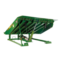
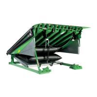
Introduction to the dock leveler's design and purpose.
Warnings about operating the leveler when personnel are present or near moving parts.
Initial steps before operating the dock leveler, including vehicle positioning and chocking.
Note directing to below dock control instructions if the vehicle is below dock level.
Procedures for extending the dock leveler lip into the vehicle and proceeding with loading/unloading.
Steps to return the dock leveler to its stored position after loading or unloading.
Critical warning about returning the leveler to stored position to prevent unexpected drops.
Instructions for using Below Dock Control (BDC) for end loading below dock level.
Instructions for dock levelers equipped with the Auto-Return to Dock option.
General warning to read safety practices and use by trained operators only.
Introduction to the Auto-Return to Dock option's functionality.
Warnings about operating the leveler when personnel are present or near moving parts.
Initial steps before operating the dock leveler with Auto-Return, including vehicle positioning.
Note directing to below dock control instructions if the vehicle is below dock level.
Procedures for extending the dock leveler lip and proceeding with loading/unloading with Auto-Return.
Steps to return the dock leveler to stored position and turn off the system.
Critical warning about returning the leveler to stored position to prevent unexpected drops.
Instructions for using Below Dock Control (BDC) with Auto-Return for end loading.
Inspect safety labels and tags quarterly for legibility and presence, replace if missing.
Critical safety warning before entering the pit or performing maintenance.
Warning to read safety and operation instructions before servicing.
Notice regarding the use of specified lubricants and potential operational issues.
Instructions for checking the hydraulic fluid level using the dipstick.
Chart detailing lubrication and cleaning intervals for various components.
Identifies lubrication points and types of lubricants to use.
Legend explaining symbols used for lubrication and visual inspection tasks.
Warning to read safety and operation instructions before servicing.
Critical safety warning before entering the pit or performing maintenance.
Steps for securing the leveler with the maintenance strut.
Instructions for engaging and disengaging the lip lock.
Critical safety warning before entering the pit or performing maintenance.
Warning to read safety and operation instructions before servicing.
Troubleshooting steps for when the ramp fails to raise, covering motor and electrical issues.
Troubleshooting steps for when the lip fails to extend, covering cylinders, hoses, and pressure.
Troubleshooting for lip extending prematurely before the ramp is fully raised.
Troubleshooting for the lip failing to drop when the ramp is raised from a vehicle.
Troubleshooting for the ramp not returning to the stored position from below dock.
Note about the return to dock level switch function.
Troubleshooting for issues with the ramp lock during downward travel.
Troubleshooting for dock level supports not retracting for below dock operation.
Troubleshooting for dock level support legs not swinging forward properly.
Troubleshooting for the lip plate not staying out or falling during lowering.
Diagram illustrating the hydraulic components and their connections.
Instructions for replacing the control box transformer in 3-phase units.
Procedures for removing and installing hydraulic oil hoses.
Critical safety warning before entering the pit or performing maintenance.
Steps for setting the downward speed of the ramp by adjusting the needle valve.
Guidance on how to identify the correct replacement parts needed.
Warning about using only approved replacement parts to maintain safety and function.
Disclaimer regarding liability for failure to comply with warnings.
Illustrations and chart for determining model number and nominal size.
Exploded view of ramp, lip, and toe guard assemblies for Model HK.
Exploded view of ramp, lip, and toe guard assemblies for Model HK-S.
Part numbers for lips by capacity, width, and degree bend.
Part number for the lip shaft.
Part numbers for bottom sliding toe guards for 19" pits.
Part numbers for below dock control chains.
Part number for the dock level support.
Exploded view of subframe and maintenance strut assemblies.
Part numbers for maintenance posts of various lengths and backframes.
Parts list for the optional subframe riser kit.
Exploded view of hydraulic components and return to dock level switch.
Part number for the motor/pump unit, including associated items.
Part number for the hydraulic hose for the ramp cylinder.
Part numbers for the ramp cylinder based on length.
Part number for the lip lifter.
Part number for the AC inductive proximity switch.
Part number for the ARTD proximity switch assembly.
Part number for the adjustable needle valve.
Exploded view and part numbers for the optional Energy Guard sealing system.
Part numbers for standard control box assemblies (120V, 208-230V).
Part number for the plastic control panel enclosure.
Part number for the 120V contactor.
Part numbers for standard control box assemblies (208-240V, 460-480V, 575V).
Part numbers for standard control box assemblies (208-230V, 460-480V, 575V).
Part number for the overload relay for 208-230V.
Part numbers for control box assemblies with optional interlock (120V).
Part numbers for control box assemblies with optional interlock (120V).
Part number for the overload relay (12-18 Amps).
Part numbers for control box assemblies with optional interlock (208/240V).
Part numbers for control box assemblies with optional interlock (208/240V).
Part number for the overload relay (9-13 Amps).
Part numbers for control boxes with interlock and auto-return (208V, 240V).
Part numbers for control boxes with interlock and auto-return (208V, 240V, 480V).
Part number for the overload relay (4-6 Amps).
Part numbers for control boxes with interlock and auto-return (575V).
Part numbers for control boxes with interlock and auto-return (575V).
Part number for the overload relay (4-6 Amps).
Part numbers for control boxes with interlock and auto-return (120V).
Part numbers for control boxes with interlock and auto-return (120V).
Part number for the Kelley HP/HK-2PB decal.
Part numbers for control boxes with interlock and auto-return (208/240V).
Part numbers for control boxes with interlock and auto-return (208/240V).
Part number for the schematic of a 2-position push button control.
Part numbers for control boxes with interlock and auto-return (208V, 240V, 480V).
Part numbers for control boxes with interlock and auto-return (208V, 240V, 480V).
Part number for the schematic of a 2-position push button control.
Part numbers for control boxes with interlock and auto-return (575V).
Part numbers for control boxes with interlock and auto-return (575V).
Part number for the schematic of a 2-position push button control.
States the scope and limitations of the limited warranty for Model HK.
Details the extended warranty period for hydraulic power units and cylinders.
Outlines Kelley's options for remedying deficiencies in material or workmanship.
States the scope and limitations of the limited warranty for Model HK-S.
Details the extended warranty period for hydraulic power units and cylinders.
Outlines Kelley's options for remedying deficiencies in material or workmanship.
Provides contact information for local distributors and the corporate head office.
| Brand | Kelley |
|---|---|
| Model | HK-S |
| Category | Lifting Systems |
| Language | English |