© 2017 Kelso Technologies (USA) Inc. All Kelso Valves are Patent Protected. Detailed designs are subject to change without notice.
Kelso Technologies Inc. 1526 Texas Ave, Bonham, TX. 75418, Phone: (903) 583-9200
6.0 Pressure Testing and Adjustment
Refer to AAR publication “Regulations for Tank Cars”. Appendix A applies
specifically to valves. This section prescribes the start to discharge pressure
(STD), the vapor tight pressure (VTP), their tolerances, and the processes
associated with achieving the desired values.
6.1 Procedure
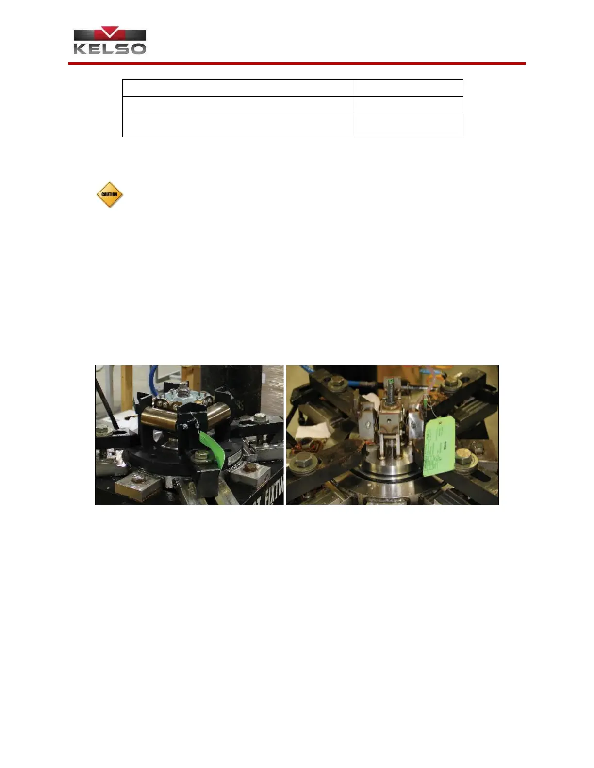
1. After the appropriate gasket style has been determined and applied to the
test stand, securely clamp the valve onto the test stand (Figure 6.1 and 6.2).
Rotate the adjustment screw counterclockwise to lower the spring block,
approximately halfway between the initial spring engagement location and the
dwell location. Raise the pressure in the test stand and leak test the mating
surface between the valve flange and the test stand, as well as any test stand
fittings to ensure the device is not losing air at any point. Release the air from
the test stand. If any leaks exist, repair them, and retest the system.
2. Spray the valve sealing disc with water or suitable leak test fluid until a
continuous film of water is observed at the intersection of the sealing disc and
the valve body (Figure 6.3 & 6.4). Maintain this film throughout the tests.
Raise the pressure in the test stand until the first bubble is observed. The
pressure at which this occurs is the start to discharge pressure (Figure 6.5 &
6.6).
 Loading...