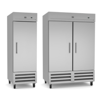
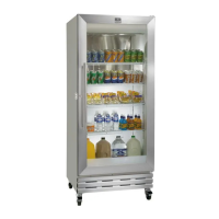
3 REACH-INS REFRIGERATORS/FREEZERS
compressor oil to flow back into place. Failure to meet this requirement can
cause compressor failure and unit damage.
ELECTRICAL CONNECTION: Refer to the amperage data on page 1, the serial tag,
your local code or the National Electrical Code to be sure the unit is connected
to the proper power source.
OPERATION
CAUTION: DO NOT THROW ITEMS INTO THE STORAGE AREA. FAILURE TO HEED THESE
RECOMMENDATIONS COULD RESULT IN DAMAGE TO THE INTERIOR OF THE
CABINET.
REFRIGERATED CYCLE
Refrigerators: During the refrigeration cycle, the evaporator fans wilt run
continuously even when one or more doors are open. The door switch will activate
the lights when opened.
1. Every 6 hours, the unit will turn off and to allow the evaporator coil to defrost. The
controller now displays defrost symbol. When the coil temperature reaches 41°F
or after 20 minutes of defrost, the unit will turn on again.
2. Anti-condensation heaters on door frames work in conjunction with the
compressor.
3. The factory setting for the temperature range is 34°F to 38° F.
Freezers:
During the refrigeration cycle, the controller supplies power to the
condensing unit and evaporator fan motors. The evaporator fans will run at any time
when the evaporator coil temperature is below 54°F. They will also keep running
when door is open but cycle off during a defrost period. The door switch will activate
the lights when opened.
1. Every 6 hours, the unit will turn off and electric heater will turn on to defrost. The
controller now displays the defrost symbol. When the coil temperature reaches
45°F or after 20 minutes of defrost, the unit will turn on again.
2. Anti-condensation heaters on door frames work in conjunction with the
compressor.
3. The factory setting for temperature range is -7 to -3°F
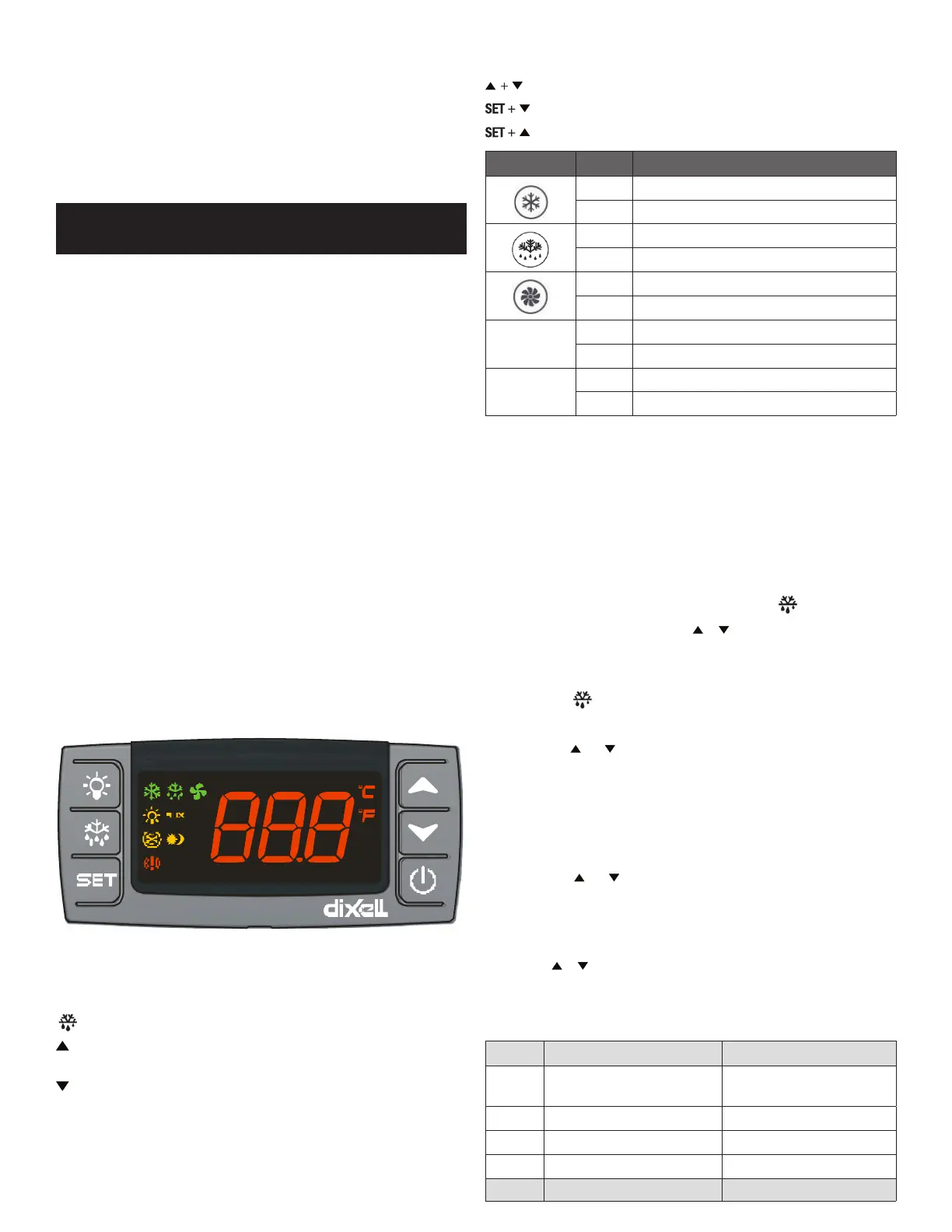
CONTROL PANEL SOLID-STATE THERMOSTAT
FRONT PANEL COMMANDS
SET SET: To display target set point; in programming mode it selects a
parameter or conrms an operation.
DEF: To start a manual defrost
UP: To view the last alarm occurrence; in programming mode it browses
the parameter codes or increases the display value
DOWN: To view the last alarm occurrence; in programming mode it
browses the parameter codes or decreases the display value
Key Combination:
To lock & unlock the keyboard
To enter in programming mode
To return to the room temperature display
LED MODE FUNCTION
On Compressor enabled
Flashing Anti-short cycle delay enabled (AC parameter)
On Defrost in progress
Flashing Dripping in progress
On Fans output enabled
Flashing Fans delay after defrost
ºC
On Measurement unit
Flashing Programming mode
ºF
On Measurement unit
Flashing Programming mode
MAIN FUNCTIONS
1. How To See The Setpoint
1. Push and immediately release the SET key: the display will show the set
point value.
2. Push and immediately release the SET key or wait for 5 seconds to display
thesensor value again.
2. How To Change The Setpoint
1. Hold the SET key for more than 2 seconds to change the set point value.
2. The value of the set point will be displayed and the
LED starts blinking.
3. To change the set value, push the or key within 10s.
4. To set new point value, push the SET key again or wait 10s.
3. How To Start A Manual Deffrost
1. Hold the
key for more than 2 seconds and a manual defrost will start
4. How To Lock The Keyboard
1. Hold the and keys for more than 3s.
2. The “POF” message will be displayed and the keyboard will be locked. At
this point, it will be possible only to see the set point or the MAX or MIN
temperature stored.
3. If a key is pressed more than 3s the ”POF” message will be displayed.
5. How To Unlock The Keyboard
1. Hold the and keys together for more than 3s until the “POF” message
is displayed.
ALARM SIGNALS
How To See The Alarm And Reset The Recorded Alarm
1. Push the or key to display the alarm signals.
2. When the signal is displayed, hold the SET key until the “rst” message is
displayed, and push the SET key again. The “rst” message starts blinking and the
normal temperature will be displayed.
MESSAGE CAUSE OUTPUTS
“P1” Room probe failure
Compressor output according
to par. “Con” and “COF”
“P2” Evaporator probe failure Defrost end is timed
“HA” Maximum temperature alarm Outputs unchanged
“LA” Minimum temperature alarm Outputs unchanged
MESSAGE CAUSE OUTPUTS
 Loading...