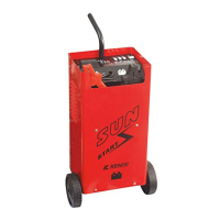
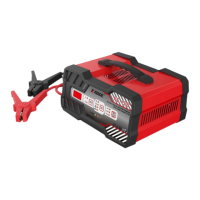
This document describes a series of CD Battery Chargers, including models CD-220, CD-320, CD-420, CD-520, and CD-620, manufactured by Zhejiang Kende Mechanical & Electrical CO., LTD. These chargers are designed for charging and starting lead-acid batteries for motorcycles, automobiles, tractors, and ships.
Function Description
The CD Battery Charger series offers an auxiliary function for start-up, allowing it to be used for both charging and starting lead-acid batteries. It is equipped with an input fuse and an output fuse, and a grounding wire connected to the power cables for enhanced safety and reliability. The chargers feature controlling switches for adjusting charging current and startup current, providing full functionality. For ease of movement and operation, the devices are installed with two wheels and a handle.
Important Technical Specifications
The technical specifications vary slightly across the different models:
CD-220:
- Standard: EN60335-2-29
- Certification: TÜV Rheinland ZERTIFIZIERT, GS geprüfte Sicherheit
- Input: 230V~50Hz, 605W, 1.7/3.1A
- Output: 12.0V d.c., 16A; 24.0V d.c., 18A
- Battery Capacity: Min. 70Ah, Max. 300Ah
- Boost Current (I₂boost): 20A
- Minimum Current (I2min): 12A
- Start Current: 130A (3S ON, 120S OFF)
- Fuses: 15A (INPUT), 2x80A (OUTPUT)
- Protection Class: IP20
CD-320:
- Standard: EN60335-2-29
- Certification: TÜV Rheinland ZERTIFIZIERT, GS geprüfte Sicherheit
- Input: 230V~50Hz, 810W, 2.1/3.9A
- Output: 12.0V d.c., 20A; 24.0V d.c., 22A
- Battery Capacity: Min. 80Ah, Max. 450Ah
- Boost Current (I₂boost): 30A
- Minimum Current (I2min): 15A
- Start Current: 170A (3S ON, 120S OFF)
- Fuses: 20A (INPUT), 3x80A (OUTPUT)
- Protection Class: IP20
CD-420:
- Standard: EN60335-2-29
- Certification: TÜV Rheinland ZERTIFIZIERT, GS geprüfte Sicherheit
- Input: 230V~50Hz, 920W, 2.2/4.3A
- Output: 12.0V d.c., 25A; 24.0V d.c., 27A
- Battery Capacity: Min. 100Ah, Max. 600Ah
- Boost Current (I₂boost): 40A
- Minimum Current (I2min): 17A
- Start Current: 250A (3S ON, 120S OFF)
- Fuses: 20A (INPUT), 3x80A (OUTPUT)
- Protection Class: IP20
CD-520:
- Standard: EN60335-2-29
- Certification: TÜV Rheinland ZERTIFIZIERT, GS geprüfte Sicherheit
- Input: 230V~50Hz, 1050W, 2.6/4.6A
- Output: 12.0V d.c., 25A; 24.0V d.c., 30A
- Battery Capacity: Min. 120Ah, Max. 750Ah
- Boost Current (I₂boost): 50A
- Minimum Current (I2min): 17A
- Start Current: 300A (3S ON, 120S OFF)
- Fuses: 25A (INPUT), 4x80A (OUTPUT)
- Protection Class: IP20
CD-620:
- Standard: EN60335-2-29
- Certification: TÜV Rheinland ZERTIFIZIERT, GS geprüfte Sicherheit
- Input: 230V~50Hz, 1200W, 2.6/5.8A
- Output: 12.0V d.c., 30A; 24.0V d.c., 35A
- Battery Capacity: Min. 140Ah, Max. 900Ah
- Boost Current (I₂boost): 60A
- Minimum Current (I2min): 20A
- Start Current: 320A (3S ON, 120S OFF)
- Fuses: 30A (INPUT), 5x80A (OUTPUT)
- Protection Class: IP20
All models are designed for single-phase transformer-rectifier operation and include a symbol for battery connection (anode and cathode). The IP20 protection class indicates that the product is for indoor use only and should not be used in rainy or snowy conditions.
Usage Features
The user manual emphasizes several key usage features and safety regulations:
Battery Preparation:
- Before charging, check the battery's specific gravity. A specific gravity below 1.16KG/L indicates an empty battery.
- Ensure the electrolytic solution level is sufficient; if not, add distilled water until it is.
- Handle electrolytic solution (dilute sulfuric acid) with care, as it is highly corrosive. In case of skin contact, wash immediately with water and seek medical attention.
Charging Procedure:
- Connect the red anode clamp to the battery's anode and the corresponding 12V or 24V terminal on the charger.
- Connect the black cathode clamp to the battery's cathode.
- If charging a car battery, connect the charger to the terminal not connected to the chassis first, then connect the other charger terminal to the chassis, ensuring connection points are far from the battery and fuel lines.
- Insert the power plug.
- Turn the power switch to "I" (ON).
- Set the function switch to "charge."
- Select the desired current setting (MIN or MAX) using the MIN/BOOST switch.
- For CD-520 and CD-620 models, set the charging time using the "Time/Untime" function.
- During charging, monitor the electrolytic solution temperature, ensuring it does not exceed 45°C. If it does, reduce the charging current to prolong charging time and prevent continuous temperature increase.
- Charging is complete when the specific gravity is near 1.28KG/L, terminal voltage exceeds 14V (or 28V), and the solution is heavily bubbling.
- After charging, turn off the power, unplug the charger, and then remove the battery clamps.
Auxiliary Start Procedure:
- Ensure the battery has been fast-charged for 10-15 minutes using the charger.
- Connect any pole of the charger to the engine's terminal not linked to the chassis (matching polarity).
- Connect the other pole of the charger to the engine's terminal linked to the chassis.
- Refer to the engine manufacturer's instructions.
- Insert the power plug.
- Turn the power switch to "ON."
- Set the function switch to "start."
- The engine can then be started.
- Important: Each start attempt should last 3 seconds. Allow 120 seconds between the first and second start attempts. A maximum of five cycled starts are available. If continuous starting is required, ensure a 10-minute interval between two start cycles to allow the internal transformer to cool down.
Safety Regulations:
- Charge batteries in a well-ventilated area, away from flames and sparks, and prohibit smoking.
- The product is for indoor use only (IP20).
- Ensure the grounding wire is reliably connected.
- Place the charger on a level surface; do not tilt or reverse it.
- Do not cover the casing's vent during charging to prevent overheating.
- Strictly follow battery and transportation tool instructions.
- Mount or dismantle the battery only after turning off the power.
- Do not contact battery clamps with each other.
- Open the battery cover during charging.
- Do not connect battery clamps in reverse (e.g., red to cathode, black to anode).
- Do not use the charger for non-rechargeable batteries.
- Replace fuses and cables with those of the same specifications. Do not use other conductors as replacements.
- Damaged power cables must be replaced by the manufacturer or qualified personnel.
- When connecting to a vehicle, connect the battery terminal not connected to the chassis first, then connect the other connection to the chassis, away from the battery and fuel line. Then connect the charger to the supply mains.
- After charging, disconnect the charger from the supply mains, then remove connections from the charger and battery.
- The product is intended for permanent connection to fixed wiring, and a disconnection incorporated in the fixed wiring must be provided.
Maintenance Features
- Regular maintenance and repair are essential for proper use and safety compliance.
- Improper operation can lead to machine failure and damage.
- The warranty period is one year from the purchase date. Users can seek repair from the distributor or designated department with the invoice.
- Before any maintenance, turn off the main power at the distribution cabinet and the machine's power switch.
- If the transformer overheats and no current is available due to overcurrent protection, wait for the transformer to cool down before resuming charging.