Do you have a question about the Kenmore 596.78079891 and is the answer not in the manual?
Specifies electrical requirements, refrigerant type, and amount for the unit.
Details compressor voltage, Btuh, watts, current, and overload protector specifications.
Outlines fan motor electrical requirements, RPMs, watts, and amps.
Provides capacitance and voltage rating for the unit's capacitor.
Instructions for checking compressor and fan motor resistance and continuity.
Procedures for testing capacitor continuity and overload protector resistance.
Guidance on checking wiring continuity for the electronic control board.
Table detailing acceptable wattage input based on air temperatures.
Chart showing acceptable current ranges for cooling operation.
Graph illustrating cooling performance based on dry bulb temperatures.
Visual representation of the unit's wiring with crucial safety warnings.
List of main components with their corresponding part numbers.
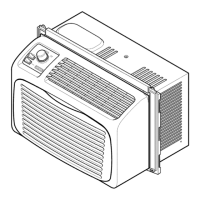
This document provides technical information for the Kenmore Room Air Conditioner, Model 596.78079891, a 6,600 Btu unit designed for cooling.
The Kenmore Room Air Conditioner is designed to cool an indoor space by removing heat and humidity from the air. It operates by circulating refrigerant through a closed system, absorbing heat from the indoor air and releasing it outdoors. The unit includes a compressor, a fan motor, a capacitor, an overload protector, and an electronic control board, all working in concert to achieve the desired cooling effect. The compressor is the heart of the cooling cycle, pressurizing the refrigerant. The fan motor drives both the indoor evaporator fan, which draws warm room air over the cold evaporator coil, and the outdoor condenser fan, which expels heat from the condenser coil to the outside. The capacitor assists in starting and running the compressor and fan motor efficiently. An overload protector is integrated into the system to safeguard the compressor from excessive temperatures or current, ensuring its longevity and safe operation. The electronic control board manages the overall operation of the unit, including fan speeds and compressor cycles, to maintain the desired room temperature.
The air conditioner is designed for straightforward operation. It requires a 115 VAC 60Hz electrical supply. The unit's cooling capacity is rated at 6,600 Btu, making it suitable for cooling medium-sized rooms. The fan motor offers multiple speed settings—low, medium, and high—allowing users to adjust the airflow and noise level according to their comfort preferences. The electronic control system incorporates a built-in delay mechanism: after plugging in the unit, there is a 3-minute delay before the compressor starts. This delay also applies between compressor cycles, ensuring optimal operation and protecting the compressor from short-cycling. This feature helps to extend the life of the compressor and maintain efficient cooling performance. The unit's design focuses on providing consistent and reliable cooling, with various components working together to regulate temperature and airflow effectively.
Maintenance of the Kenmore Room Air Conditioner involves several key procedures to ensure its continued efficient and safe operation. The document emphasizes the importance of safety during any servicing or repair, explicitly stating that an authorized technician should always be contacted due to the possibility of personal injury or property damage. For those performing authorized maintenance, critical safety warnings are provided. Before any servicing, it is imperative to disconnect power to the unit and discharge the capacitor through a 10,000 ohm resistor, unless the specific testing procedure requires power. This prevents the risk of electrical shock. Additionally, when reassembling the unit, all wires removed during disassembly must be replaced on their proper terminals to ensure correct grounding and polarization, which is crucial for electrical safety and proper function.
The document outlines specific diagnostic procedures for various components. For the compressor, technicians can check the resistance of its windings (between C and S, and C and R terminals) and test for grounds by checking continuity between the terminals and the compressor case. The fan motor can also be checked for grounds and continuity of its windings. The capacitor's functionality can be assessed by checking its resistance, observing the indicator swing on an ohmmeter, and ensuring it discharges properly. The overload protector's operation can be verified by checking its resistance at specific temperatures, ensuring it opens at higher temperatures and closes at lower ones. For the electronic control, continuity checks are performed on the wiring between the circuit board terminals and component connections. If continuity is not indicated, the wiring should be replaced before considering replacement of the electronic control board. These detailed diagnostic steps facilitate effective troubleshooting and repair, helping to identify and resolve issues efficiently. The document also refers to a Service Manual for more comprehensive operation, disassembly, testing, and troubleshooting information, and a Repair Parts List for part number details, indicating a structured approach to maintenance and repair.
| Power Supply | 115V / 60Hz |
|---|---|
| Operating Temperature | 62°F - 90°F |
| Remote Control | Yes |
| Timer | 24-hour |
| Refrigerant | R410A |
| Warranty | 1 year limited |