Do you have a question about the Kenmore 721.62642 and is the answer not in the manual?
Essential safety measures before and during servicing to prevent microwave energy exposure.
Detailed technical parameters of the microwave oven, including power, frequency, and dimensions.
Warnings and precautions related to potential microwave radiation exposure during operation and service.
Instructions and precautions for safely installing the microwave oven, including grounding.
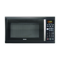
Explanation of the microwave oven's control panel layout and functions.
Descriptions of each button and sensor on the control panel and their operational functions.
A high-level schematic illustrating the overall electrical connections of the microwave oven.
A detailed schematic diagram, including noise filter considerations.
A matrix illustrating the circuit connections for the touch key board buttons.
Important safety precautions and guidelines for using the microwave oven.
Procedures for checking the oven's operation after installation or repair.
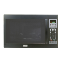
Overview of the oven's features, including safety systems and power output levels.
Critical precautions and tips for performing service and repairs on the microwave oven.
Safety warnings and procedures for checking microwave leakage before and after servicing.
Method and equipment for measuring microwave energy leakage from the oven.
Procedure for measuring microwave power output with the outer case removed.
Procedure for measuring microwave power output on a fully assembled oven.
Critical safety notes and preparation steps before disassembling the unit.
Step-by-step guide to removing the power and control circuit board.
Instructions for safely removing the Flexible Printed Circuit (FPC) connector.
Instructions for safely inserting the Flexible Printed Circuit (FPC) connector.
Detailed steps to remove the outer casing of the microwave oven.
Procedure for removing and replacing the door interlock switches.
Step-by-step instructions for safely removing the magnetron assembly.
Instructions for removing the microwave oven door.
Steps to disassemble the microwave oven door assembly.
Procedure for properly mounting and adjusting the door assembly.
Steps to remove the ventilation fan assembly from the microwave oven.
Instructions for safely removing the turntable motor.
Explanation of the door lock mechanism and its function in preventing microwave leakage.
Procedures for adjusting door latches and interlock switches for proper operation.
Tests to verify the correct sequence of interlock switches when the door is operated.
Testing the microwave energy leakage after interlock adjustments.
Procedure to check the continuity of the primary interlock switch.
Procedure to check the continuity of the secondary interlock switch.
Procedure to check the continuity of the interlock monitor switch.
Important safety precautions before performing tests and checkout procedures.
Procedures for testing the magnetron and high-voltage transformer resistance.
Procedure for testing the high-voltage capacitor's resistance and continuity.
Procedure for testing the high-voltage diode's forward and reverse continuity.
Testing the touch key board using its matrix circuit and connector.
Testing the Flexible Printed Circuit (FPC) connector for proper connection and resistance.
Checking the continuity of Relay 2 under different power levels.
Troubleshooting common causes for fuse blowing.
Diagnostic procedures for identifying relay failures (Relay 1).
Identifying common symptoms that indicate a defective circuit board.
Troubleshooting steps for display errors and incorrect programming inputs.
Diagnosing the cause when the oven does not heat up despite proper operation.
Troubleshooting issues related to the oven's buzzer not sounding or sounding continuously.
Diagnosing problems with the ventilation fan not operating when commanded.
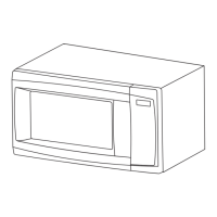
An exploded view diagram of the microwave oven's door components.
Exploded view and part list for the controller assembly, specific to model series.
Exploded view and part list for the oven cavity components, specific to model series.
Exploded view and part list for the latch board assembly.
Exploded view and part list for interior components (Part I).
Exploded view and part list for interior components (Part II - I).
Exploded view and part list for interior components (Part II - II).
Exploded view and part list for installation accessories and hardware.
| Brand | Kenmore |
|---|---|
| Model Number | 721.62642 |
| Product Type | Microwave Oven |
| Type | Countertop |
| Turntable | Yes |
| Turntable Diameter | 12.4 inches |
| Color | Stainless Steel |
| Cooking Modes | Popcorn, Potato, Reheat, Beverage, Defrost |