Do you have a question about the Kenmore 721.63682 and is the answer not in the manual?
Essential safety measures to avoid excessive microwave energy exposure during servicing.
Instructions on careful manual reading to prevent exposure to microwave energy.
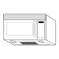
Detailed technical data including power, dimensions, and components.
Safe installation procedures and importance of proper grounding for the appliance.
Detailed explanation of each button and its function on the control panel.
Specific descriptions for each button on the control panel.
Comprehensive electrical schematic illustrating component connections and layout.
Specific matrix circuit diagram for the touch key board functionality.
Essential precautions during use of the microwave oven.
Procedures for trial operation after installation to check functionality.
Crucial precautions and practical tips for technicians performing repairs.
Details on necessary equipment and the step-by-step process for microwave leakage testing.
Methods for measuring microwave energy leakage and power output.
Step-by-step guide to removing the power and control circuit board.
Instructions for safely removing and inserting FPC connectors.
Procedure for removing the outer casing of the microwave oven.
Steps for detaching and removing the door interlock switch components.
Guide for removing the magnetron and the inverter module.
Steps to remove the stirrer fan, door, and disassemble the door assembly.
Procedures for removing the ventilation motor and assembling the door.
Detailed steps for removing the turntable motor assembly.
Steps for adjusting door latches and interlock switches for proper operation.
Procedures to test the operational sequence of door latch and interlock switches.
Methods for checking the continuity of primary, secondary, and monitor interlock switches.
Procedures for testing key components like sensors, motors, and key matrix.
Checkout steps for problems like fuse blowing, relay issues, and circuit board symptoms.
Diagnosing and resolving issues such as no operation, sparks, uneven cooking, or low output.
Illustrated breakdown of parts for the microwave door assembly.
Visual identification of parts related to the control unit.
Exploded view of parts within the main oven cavity.
Diagram showing the individual parts of the latch board assembly.
Illustrated view of various interior components.
Further illustration of interior parts for the appliance.
Visual representation of parts used during the installation process.
Detailed schematic diagram of the printed circuit board (PCB).
| Brand | Kenmore |
|---|---|
| Model Number | 721.63682 |
| Product Type | Microwave Oven |
| Power | 1000 Watts |
| Color | Stainless Steel |
| Cooking Levels | 10 |
| Turntable Diameter | 12.4 inches |
| Preset Cooking Programs | Yes |
| Child Safety Lock | Yes |
| Turntable | Yes |
| Cooking Modes | Microwave |