EasyManua.ls Logo

Kenmore 795.71012.010 User Manual

Kenmore 795.71012.010
46 pages
To Next Page IconTo Next Page
Page #1 background imageLoading...
Page #1 background image
CAUTION
BEFORE SERVICING THE UNIT,
READ THE SAFETY PRECAUTIONS IN THIS MANUAL.
Model #s:
REFRIGERATOR
SERVICE MANUAL
795.71012.010
795.71013.010
795.71014.010
795.71016.010
795.71019.010
P/No. MFL63293901
Question and Answer IconNeed help?

Do you have a question about the Kenmore 795.71012.010 and is the answer not in the manual?

Kenmore 795.71012.010 Specifications

General IconGeneral
BrandKenmore
Model Number795.71012.010
CategoryRefrigerator
TypeFrench Door
Ice MakerYes
Water DispenserYes
Energy Star CertifiedYes
Defrost TypeFrost-Free
ColorStainless Steel

Summary

1. SPECIFICATIONS

1-1 DISCONNECT POWER CORD BEFORE SERVICING

Safety instruction to disconnect power before any servicing is performed.

1-2 IMPORTANT NOTICE

Disclaimer regarding experience required and liability for repair attempts.

1-3 ELECTRICAL SPECIFICATIONS

Details on voltage, current, and energy consumption ratings for the appliance.

1-4 NO LOAD PERFORMANCE

Performance data for the refrigerator under no-load conditions at specific ambient temperatures.

1-5 REFRIGERATION SYSTEM

Technical specifications for the refrigeration system, including vacuum, pressure, and refrigerant details.

1-6 INSTALLATION

Clearance requirements for proper air circulation around the refrigerator.

1-7 REPLACEMENT PARTS

List of common replacement parts with their part numbers.

1-8 AIR FLOW / CIRCULATION D'AIR

Diagram illustrating the air flow and circulation within the refrigerator.

1-9 DIMENSIONS

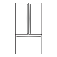
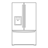
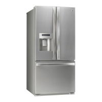
Detailed physical dimensions of the refrigerator with various measurements.

2. PARTS IDENTIFICATION

3. DISASSEMBLY

3-1 REMOVING AND REPLACING REFRIGERATOR DOORS

Step-by-step guide for safely removing and reinstalling refrigerator doors.

3-2 DOOR

Door Gasket Removal

Instructions for removing the door gasket from the refrigerator door frame.

Door Gasket Replacement

Steps for correctly installing a new door gasket into the door frame.

3-3 TO REMOVE THE DISPENSER

3-4 DOOR ALIGNMENT

3-5 FAN AND FAN MOTOR

3-6 DEFROST CONTROL ASSEMBLY

3-7 LAMP

3-7-1 Refrigerator Compartment Lamp

Procedure for replacing the light bulb in the refrigerator compartment.

3-7-2 Freezer Compartment Lamp

Procedure for replacing the light bulb in the freezer compartment.

3-8 MULTI DUCT

3-9 HOW TO REMOVE AND REINSTALL THE PULLOUT DRAWER

3-9-1 FOLLOW STEPS TO REMOVE

Detailed steps for the safe removal of the pullout drawer from the freezer.

3-9-2 FOLLOW STEPS TO REINSTALL

3-9-3 PULL OUT DRAWER

4. ADJUSTMENT

4-1 COMPRESSOR

Explanation of the compressor's role, composition, and usage precautions.

4-2 PTC-STARTER

Details on the PTC starter's composition, role, circuit, and usage notes.

4-3 OLP (OVERLOAD PROTECTOR)

4-4 TO REMOVE THE COVER PTC

5. CIRCUIT DIAGRAM

6. TROUBLESHOOTING

6-1 COMPRESSOR AND ELECTRIC COMPONENTS

Troubleshooting flowchart for compressor and related electrical components.

6-2 OTHER ELECTRICAL COMPONENTS

6-3 SERVICE DIAGNOSIS CHART

6-4 REFRIGERATION CYCLE

Troubleshooting Chart

Chart to diagnose refrigeration issues based on cause, unit state, and temperature.

6-4-1 SEALED SYSTEM DIAGNOSIS

7. ICE MAKER AND DISPENSER WORKING PRINCIPLES AND REPAIR

7-1 Working Principles

Overview of the ice maker's operational sequence and controls.

7-2 Function of Ice Maker

7-2-1 Initial Control Function

Description of the ice maker's initial control sequence upon power application.

7-2-2 Water Supply Control Function

Explanation of how water is supplied to the ice maker mold based on DIP switches.

7-2-3 Ice Making Control Function

Details on how the ice maker controls the ice making process based on temperature.

7-2-4 Ice Ejection Control Function

7-2-5 Test Function

8. DESCRIPTION OF FUNCTION & CIRCUIT OF MICOM

8-1 FUNCTION

Overview of the refrigerator's main functions controlled by the MICOM system.

8-1-6 CONTROL OF FREEZER FAN MOTOR

8-1-7 Ultra Ice

8-1-8 REFRIGERATOR LAMP AUTO OFF

8-1-9 Alarm for Open Door

8-1-10 Buzzer Sound

8-1-11 Defrost cycle

8-1-12 Filter Replacement Indication

8-1-13 DISPENSER LIGHT

8-1-14 Automatic Diagnosis Function

8-1-15 TEST Mode

8-2 PCB FUNCTION

8-2-1 Power Circuit

Diagram and explanation of the power circuit supplying various components.

8-2-2 Oscillation Circuit

8-2-3 Reset Circuit

8-2-4 Load / Buzzer Drive & Open Door Detection Circuit

1. Load Drive Condition Check

Table showing output voltages for various circuits during load drive checks.

2. Fan motor driving circuit (freezing compartment fan, mechanical room)

Explanation of the fan motor driving circuit and its speed control.

3. Open Door Detection Circuit Check

8-2-5 Temperature Sensor Circuit

8-2-6 Refrigeration Compartment Stepping Motor Damper Circuit

8-3 RESISTANCE SPECIFICATION OF SENSOR

8-4 TROUBLESHOOTING

POWER SOURCE is poor.

Troubleshooting steps for issues related to the refrigerator's power source.

DISPLAY LCD operates abnormally

Troubleshooting steps for abnormal operation of the display LCD.

COOLING is poor.

Troubleshooting steps for poor cooling performance in the refrigerator.

FREEZER TEMPERATURE is incorrect

Troubleshooting steps for incorrect freezer temperature readings or performance.

COOLING is poor.

DEFROSTING is poor.

8-5 MAIN PWB ASSEMBLY AND PARTS LIST

8-5-1 Main PWB Assembly

Diagram of the main Printed Circuit Board (PCB) assembly with component locations.

REPAIR PARTS LIST

ICEMAKER PARTS

List of parts for the ice maker assembly with part numbers.

CASE PARTS

CASE PARTS

CASE PARTS

REFRIGERATOR PARTS

REFRIGERATOR PARTS

DOOR PARTS

DISPENSER PARTS

Related product manuals