Do you have a question about the Kenmore 795. 72063.11 series and is the answer not in the manual?
Safety procedure for disconnecting power before servicing the unit.
Notice regarding the intended use and liability for this manual's information.
Details electrical ratings, temperature controls, and energy consumption of the refrigerator.
Specifies performance data under no-load conditions at different ambient temperatures.
Lists specifications for the refrigeration system, including vacuum and pressure.
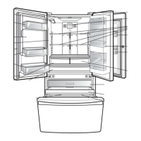
Provides clearance requirements for installation and air circulation.
Lists common replacement parts and their corresponding part numbers.
Illustrates the air circulation paths within the refrigerator and freezer compartments.
Step-by-step instructions for removing and replacing the refrigerator doors.
Details procedures for removing/replacing mullions and door gaskets.
Instructions on how to align refrigerator doors for proper closure and appearance.
Procedures for disassembling and replacing fan motors in freezer and refrigerator compartments.
Explains the function and replacement of defrost control assemblies.
Instructions for replacing refrigerator compartment lamps and LED lights.
Steps for removing and reinstalling the multi duct and cap duct LED lamp.
Guide on replacing air filter, main PCB, and dispenser cover.
Procedures for replacing display PCB, funnel, sub PCB, cap duct, and motor.
Steps for replacing the ice corner door and icemaker unit.
Instructions for removing and placing the ice bin.
Instructions for removing and reinstalling the top and middle drawers.
Detailed steps for removing and reinstalling the main pull-out drawer system.
Methods for disassembling water valve and fan motor assemblies.
Precautions for sealed system repair and 3-way valve service.
Instructions for servicing homebar, homebar door, and related cover parts.
Explains the role of the compressor and provides notes for usage and removal.
Lists error codes, their detection categories, display, generation factors, and remarks.
Shows a picture and part number for the main PCB.
Displays pictures and part numbers for the display PCB and sub PCB.
Troubleshooting steps for freezer sensor errors, including resistance checks.
Troubleshooting steps for refrigerator sensor errors, including resistance checks.
Troubleshooting steps for icing sensor errors, including resistance checks.
Troubleshooting steps for defrost sensor errors, including resistance checks.
Troubleshooting steps for defrost sensor errors, including resistance checks.
Troubleshooting steps for defrost heater errors, including resistance and voltage checks.
Troubleshooting steps for defrost heater errors, including resistance and voltage checks.
Troubleshooting steps for refrigerator fan errors, including voltage and airflow checks.
Troubleshooting steps for freezer fan errors, including voltage and airflow checks.
Troubleshooting steps for icing fan errors, including voltage and connector checks.
Troubleshooting steps for condenser fan errors, including voltage and rotation checks.
Troubleshooting steps for communication errors between PCBs, checking wire connections.
Troubleshooting steps for when the cube mode dispensing function fails.
Troubleshooting steps for when the crush mode dispensing function fails.
Troubleshooting steps for when the water dispensing function fails.
Steps to troubleshoot why the freezer compartment lamp is not working.
Steps to troubleshoot why the refrigerator compartment lamp is not working.
Troubleshooting guide for insufficient cooling in the fresh food compartment.
Troubleshooting guide for insufficient cooling in the freezer compartment.
Instructions on how to enter test mode and remove Terminal Position Assurance.
Chart showing temperature-resistance and voltage values for freezer and icing sensors.
Chart showing temperature-resistance and voltage values for refrigerator and defrost sensors.
Explanation of how the system checks for fan errors and displays error codes.
Information on testing the Fuse-M and sensor components of the defrost controller.
Procedure for testing the resistance of the sheath heater in the freezer room.
Procedure for testing the resistance of the sheath heater in the refrigerator room.
Information on testing the resistance of the door heater assembly.
Method for testing the functionality and resistance of door switches.
Procedure for testing the resistance of the dispenser DC motor.
Instructions for testing the resistance of AC motors used in the assembly.
Procedure for testing the resistance of the damper assembly.
Method for testing the resistance of the lamp socket to ensure proper connection.
Procedure for testing the resistance of the water flow sensor.
Simplified checks for the PCB related to compressor operation.
Procedures for checking the driver PCB and IPM output voltage for the compressor.
Troubleshooting based on LED blink patterns indicating compressor faults.
Detailed steps for checking compressor harness, capacitor, and resistance.
Diagnostic steps for protection logic activation and sealed system checks.
A comprehensive chart correlating complaints with points to check and remedies.
Analysis of the refrigeration cycle under various conditions like leakage or clogging.
Diagnostic flowchart for identifying issues within the sealed refrigeration system.
Explains the basic operating steps and modes of the icemaker unit.
Details the icemaking, harvest, and fill/park positions of the icemaker.
Guides on troubleshooting common ice and water system problems.
Diagnostic steps for icemaker unit and ice-detecting sensor issues.
Lists other potential causes for icemaker malfunction if primary diagnosis fails.
Troubleshooting steps for issues related to the ice dispenser not working correctly.
Describes the basic functions of the refrigerator's control system and display.
Instructions on switching the temperature display between Fahrenheit and Celsius.
Explanation of how to use the alarm and button lock features on the dispenser panel.
Information on the water filter replacement indicator light and reset procedure.
Information on the air filter replacement indicator light and reset procedure.
How to select and use the air filter function, including MAX mode.
Instructions for using the Ultra Ice function for faster freezing.
Guide on selecting and using the water and ice dispenser functions.
Explains the different modes and operation of the dispenser's ambient mood light.
Description of the freezer fan motor's speed control and operation modes.
Details on the cooling fan motor's operation in conjunction with the compressor.
Information about the ice compartment fan's control and failure sensing.
Description of the refrigeration room fan motor's operation and failure sensing.
Explains the purpose and activation of the Ultra ICE function for increased ice production.
Instructions for entering and canceling the refrigerator's display mode.
How to activate and use the energy saver function for reduced power consumption.
Details on how and when the defrosting cycle operates and its stopping conditions.
Information on the automatic diagnosis system for detecting and displaying defects.
Description of the auto pantry function for temperature control.
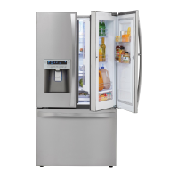
| Style | French Door |
|---|---|
| Color | Stainless Steel |
| Number of Doors | 3 |
| Total Capacity | 25 |
| Refrigerator Capacity | 18 |
| Freezer Capacity | 61 cu ft |
| Number of Refrigerator Shelves | - |
| Number of Refrigerator Bins | 1 Fixed |
| Humidity Controlled Crispers | - |
| Number of Freezer Shelves/Baskets | - |
| Refrigerator Temperature | - |
| Freezer Temperature | -6°F to +8°F |
| (-14°C) | - |
| Refrigerator Special Features | External Filtered Water and Ice Dispenser |
| Freezer Special Features | - |
| Defrost System | Frost-free (Automatic) |
| Noise level | - |
| Refrigerant | R134a |
| Energy Class | - |
| Annual Energy Consumption | 578 kWh |
| Voltage | 115 V |
| Frequency | 60Hz |
| Current | - |
| Depth | 28 |
|---|---|
| Height | 70 |
| Width | 35 |
| Net Weight | - |