EasyManua.ls Logo

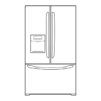
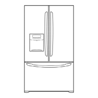
Kenmore 795.75196401 User Manual

Kenmore 795.75196401
42 pages
To Next Page IconTo Next Page
Page #1 background imageLoading...
Page #1 background image
CAUTION
BEFORE SERVICING THE UNIT,
READ THE SAFETY PRECAUTIONS IN THIS MANUAL.
REFRIGERATOR
SERVICE MANUAL
R
Model #s:
795.75192401
795.75199401
795.75194401
795.75193401
795.75196401
P/No. 3828JL8028A (Last Revision: DECEMBER. 17. 2004)
https://appliancetechmanuals.com

Questions and Answers:

Kenmore 795.75196401 Specifications

General IconGeneral
BrandKenmore
Model Number795.75196401
CategoryRefrigerator
TypeFrench Door
Ice MakerYes
Water DispenserYes
ColorStainless Steel
Energy Star CertifiedYes
Width35.75 inches
Defrost TypeFrost-Free

Summary

Specifications

1-1 DISCONNECT POWER CORD BEFORE SERVICING

Safety procedure for disconnecting power and grounding.

1-2 IMPORTANT NOTICE

Disclaimer regarding service and liability.

1-3 ELECTRICAL SPECIFICATIONS

Technical electrical specifications of the refrigerator.

1-4 NO LOAD PERFORMANCE

Performance data when the refrigerator is not loaded.

1-5 REFRIGERATION SYSTEM

Details on the refrigeration system components and capacities.

1-6 INSTALLATION

Guidelines for proper installation clearances.

1-7 REPLACEMENT PARTS

List of part numbers for common replacement components.

1-8 AIR FLOW / CIRCULATION D'AIR

Diagram illustrating the internal air circulation.

Parts Identification

Disassembly

3-1 REMOVING AND REPLACING REFRIGERATOR DOORS

Procedure for removing and installing refrigerator doors.

3-2 DOOR

Detailed steps for door gasket removal and replacement.

3-3 TO REMOVE THE DISPENSER

Instructions for safely removing the dispenser unit.

3-4 DOOR ALIGNMENT

Steps to properly align refrigerator doors for a flush fit.

3-5 FAN AND FAN MOTOR

Steps for disassembling the fan and motor assembly.

3-6 DEFROST CONTROL ASSEMBLY

Procedure for removing the defrost control assembly.

3-7 LAMP

Instructions for replacing refrigerator and freezer compartment lamps.

3-8 CONTROL BOX-REFRIGERATOR

Procedure for removing the refrigerator control box.

3-9 MULTI DUCT

Steps to remove the refrigerator's multi duct component.

Adjustment

4-1 COMPRESSOR

Details on the compressor's role, composition, and usage notes.

4-2 PTC-STARTER

Information on PTC starter composition, role, and relation to OLP.

4-3 OLP (OVERLOAD PROTECTOR)

Definition and role of the Overload Protector (OLP).

4-4 TO REMOVE THE COVER PTC

Steps for removing the PTC cover from the compressor.

Circuit Diagram

Troubleshooting

6-1 COMPRESSOR AND ELECTRIC COMPONENTS

Troubleshooting flow for compressor and electrical parts.

6-2 PTC AND OLP

Troubleshooting procedures for PTC and OLP components.

6-3 OTHER ELECTRICAL COMPONENTS

Troubleshooting for other electrical components.

6-4 SERVICE DIAGNOSIS CHART

Chart for diagnosing common refrigerator complaints.

6-5 REFRIGERATION CYCLE

Troubleshooting chart for the refrigeration cycle.

6-5-1 SEALED SYSTEM DIAGNOSIS

Flowchart for diagnosing sealed system issues.

Operation Principle and Repair Method of Icemaker

7-1 OPERATION PRINCIPLE

Step-by-step operation of the icemaker.

7-2 CONTROL METHOD ACCORDING TO FUNCTIONS

Control methods for icemaker functions like start, making, harvest.

7-2-4 Fill / Park Position

Details on filling and park positions for the icemaker.

7-2-5 Function TEST

Procedure for testing icemaker functions.

7-3 DEFECT DIAGNOSIS FUNCTION

Error codes for the ice maker water supply control panel.

Description of Function & Circuit of MICOM

8-1 FUNCTION

Overview of refrigerator functions like temperature, lock, and filter.

8-1-6 CONTROL OF FREEZER FAN MOTOR

Details on freezer fan motor control and speeds.

8-1-7 EXPRESS FREEZING

Explanation of the express freezing function and its operation.

8-1-8 REFRIGERATOR LAMP AUTO OFF

Function of automatic refrigerator lamp shut-off after prolonged door opening.

8-1-9 Alarm for Open Door

Explanation of the door open alarm system and its behavior.

8-1-10 Buzzer Sound

Description of buzzer sounds produced by the unit.

8-1-11 Defrost cycle

Information on the defrost cycle initiation and termination.

8-1-12 Filter Replacement Indication

How the water filter replacement indicator works.

8-1-13 Automatic Diagnosis Function

Explanation of the automatic diagnosis feature for servicing.

8-1-14 TEST Mode

Operation and procedures for the test mode.

PCB Function

8-2-1 Power Circuit

Details on the power supply to the control board.

8-2-2 Load / Buzzer Drive & Open Door Detection Circuit

Circuits for load drive, buzzer, and door detection.

8-2-3 Temperature Sensor Circuit

Details on the temperature sensor circuits and resistance values.

Troubleshooting

POWER SOURCE is poor.

Troubleshooting for power source issues.

COOLING is poor.

Troubleshooting for poor cooling performance.

FREEZER TEMPERATURE is incorrect

Troubleshooting for incorrect freezer temperature.

COOLING is poor.

Troubleshooting poor cooling when freezer temp is normal.

DEFROSTING is poor.

Troubleshooting for defrosting issues.

Main PWB Assembly and Parts List

8-4-1 Main PWB Assembly

Diagram of the main PWB assembly.

Repair Parts List

Model Information and Ordering

Model applicability, contact info, and ordering requirements.

ICE MAKER PARTS

Detailed list of ice maker components and their part numbers.

Case Parts

Freezer Parts

Refrigerator Parts

Door Parts

Related product manuals