Do you have a question about the Kenmore 795.75313.900 and is the answer not in the manual?
Crucial safety instruction to disconnect power before performing any service.
Details electrical ratings, leakage, ground path resistance, and energy consumption.
Lists part numbers for common replacement components.
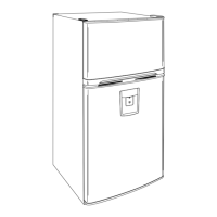
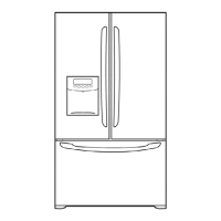
Step-by-step instructions for removing and disassembling the refrigerator doors.
Explains the compressor's role, composition, and important usage notes.
Describes PTC-Starter and Combo TSD, their composition, roles, and circuits.
Troubleshooting flowchart for compressor and related electric components.
A chart listing complaints, symptoms, causes, and solutions for diagnosis.
Outlines the step-by-step operation principle of the icemaker.
Describes the initial setup, temperature control, and defrost cycle.
Explains how error codes are displayed and what they mean.
Explains how to use the test mode for checking product functions and defects.
Details the power supply circuit to the control board.
Details the temperature sensor circuits and their voltage specifications.
| Brand | Kenmore |
|---|---|
| Model | 795.75313.900 |
| Category | Refrigerator |
| Language | English |