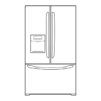
Do you have a question about the Kenmore 795.75082.401 and is the answer not in the manual?
Critical safety instruction: disconnect power cord and reconnect grounding devices before servicing.
Details electrical ratings, performance data under different ambient temperatures.
Covers refrigeration system specs and installation clearance requirements.
Lists replacement parts with their corresponding part numbers.
Illustrates the air flow path within the refrigerator for cooling.
Exploded view identifying components specific to the freezer drawer model.
Step-by-step instructions for removing doors and door switches.
Procedures for removing fan, defrost control, and replacing lamps.
Steps for removing the refrigerator control box and multi duct.
Details compressor function, composition, PTC starter role, and usage notes.
Defines OLP, its role, and provides steps to remove the PTC cover.
Specifies the type of circuit diagram shown for dispenser models.
Troubleshooting steps for compressor and electric components.
Troubleshooting steps specific to PTC and OLP components.
A chart to diagnose common complaints and their remedies.
Troubleshooting for problems within the refrigeration cycle.
Explains the 5 steps of the ice maker's operation cycle.
Details control methods for start, ice making, harvest, and fill/park positions.
Lists error codes displayed on the ice maker control panel.
Describes ice making, harvest, and fill/park functions and their parameters.
Describes basic function, fan control, express freeze, and lamp auto-off.
Describes open door alarm behavior and defrosting cycle conditions.
Explains automatic diagnosis and defect code display.
Explains how to operate the test mode for checking functions and parts.
Details the power circuit of the PCB and its voltage distribution.
Explains oscillation and reset circuits for timing and initialization.
Details circuits for load drive, buzzer, and open door detection.
Explains the temperature sensor circuit and its states.
Diagnoses and resolves issues related to poor power source.
Addresses and resolves poor cooling performance issues.
Guides on how to troubleshoot when the unit is not cooling.
Steps to diagnose and fix defrosting issues.
Diagram showing the main PWB assembly and its components.
Comprehensive list of replacement parts for the main PWB.
Lists components and parts for the display PWB assembly.
Schematic diagram of the main PWB assembly.
Exploded view showing case parts with their location numbers.
Exploded views illustrating refrigerator and freezer drawer components.
Exploded view illustrating door components.
Exploded view detailing the parts of the ice maker assembly.
| Brand | Kenmore |
|---|---|
| Model Number | 795.75082.401 |
| Type | French Door |
| Ice Maker | Yes |
| Water Dispenser | Yes |
| Finish | Stainless Steel |
| Energy Star Certified | Yes |
| Width | 35.75 in. |
| Height | 69.875 inches |


 Loading...