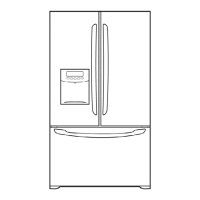
Do you have a question about the Kenmore 795.75002.402 and is the answer not in the manual?
Essential safety step before performing any service on the unit.
Information on compressor vacuum, pressure, refrigerant, and capacity.
Troubleshooting steps for compressor and related electrical components.
Diagnosing issues related to the PTC starter and overload protector.
Troubleshooting for various other electrical components like fan motors and heaters.
A chart correlating complaints with points to check and remedies.
List of error codes and their meanings for the icemaker.
How automatic diagnosis identifies and displays refrigerator defects.
Table showing defect codes, items, contents, and remarks.
Procedures for operating and using the refrigerator's test modes.
Circuit diagram and specifications for refrigerator, freezer, and defrost sensors.
Troubleshooting steps when the power source is inadequate.
Diagnosing and resolving issues causing poor cooling performance.
Troubleshooting steps for when the refrigerator is not cooling at all.
Diagnosing incorrect freezer temperature settings.
Troubleshooting issues with the defrosting system.
Steps to take when the defrosting function is not operating.
Comprehensive list of replacement parts with part numbers and specifications.
Illustrated view of the external case components for ordering.
Illustrated view of freezer compartment parts.
Illustrated view of refrigerator compartment parts.
Illustrated view of the refrigerator's door components.
Illustrated view of the ice maker components.
| Brand | Kenmore |
|---|---|
| Model | 795.75002.402 |
| Category | Refrigerator |
| Language | English |


 Loading...