Do you have a question about the Kenmore 795.75554401 and is the answer not in the manual?
Essential safety precautions for servicing the refrigerator, covering electrical safety and handling.
Details electrical ratings, temperature control range, defrost control, and energy consumption.
A comprehensive list of available replacement parts with their corresponding part numbers.
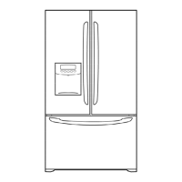
Visual guide with diagrams and labels to identify major refrigerator components.
Step-by-step guide for safely removing and reinstalling refrigerator doors, including important cautions.
Procedures for safely removing the water dispenser, including necessary tools and wire disconnection.
Detailed steps for removing the internal fan and its motor assembly for service or replacement.
Explains the compressor's role, composition, and critical handling precautions during repairs.
Details the PTC starter's composition, function in motor starting, and safe handling procedures.
Defines the OLP, its protective function for the motor, and provides a detailed cross-section diagram.
Presents the complete electrical schematic for the refrigerator, essential for troubleshooting.
Troubleshooting flowchart for diagnosing problems with the compressor and associated electrical parts.
A comprehensive chart correlating common complaints with points to check and recommended remedies.
A diagnostic flowchart specifically for addressing "Not Cooling" complaints related to the sealed refrigeration system.
Explains how the ice maker functions through a step-by-step operational principle flowchart.
Details the procedure for conducting a compulsory test to verify ice maker functions and diagnose errors.
Covers main functions like temperature control, door locks, filter indicators, and express freezing.
Details freezer fan motor control, express freezing, lamp auto-off, and door open alarm functions.
Covers buzzer sounds, defrost cycle initiation, and water filter replacement indication.
Explains the automatic diagnosis system for simplifying servicing and identifying error codes.
Provides instructions on using the Test mode to check PCB and component functionality.
Details the power supply connection to the control board.
Describes load drive conditions and open door detection circuits.
Explains the temperature sensor circuits and provides resistance values at different temperatures.
Details the circuit for the stepping motor that controls the damper.
Addresses common issues such as power, cooling, temperature, and defrosting problems with solutions.
| Brand | Kenmore |
|---|---|
| Model Number | 795.75554401 |
| Category | Refrigerator |
| Type | French Door |
| Freezer Capacity | 7.4 cu. ft. |
| Ice Maker | Yes |
| Color | Stainless Steel |
| Weight | 302 lbs |
| Water Dispenser | Yes |
| Energy Star Certified | Yes |
| Width | 35.75 inches |
| Height | 69.75 inches |
| Dimensions | 35.75 x 69.75 x 35.75 inches |