Do you have a question about the Kenmore 795.75543401 and is the answer not in the manual?
Instructions on disconnecting power and ensuring proper grounding before servicing.
Notice for individuals with adequate technical backgrounds regarding repair risks.
Details on temperature control, defrost control, and electrical ratings.
Performance data under no-load conditions for various temperatures.
Specifications for compressor capacity, pressure, refrigerant, and vacuum.
Clearance requirements for air circulation at top, sides, and rear.
List of common replacement parts with their part numbers.
Diagram illustrating the air flow and circulation within the refrigerator.
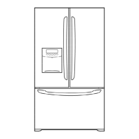
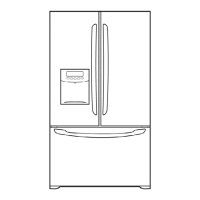
Step-by-step instructions for removing and replacing the refrigerator doors.
Procedures for removing and replacing the door gasket and frame cover.
Instructions for safely removing the dispenser unit from the refrigerator.
Steps to adjust and align the refrigerator doors for proper closure.
Procedure for removing and replacing the fan and fan motor assembly.
Details on the defrost sensor and fuse for automatic defrosting.
Instructions for replacing the refrigerator and freezer compartment lamps.
Steps for removing and accessing the refrigerator control box.
Procedure for removing the multi duct assembly.
Explains the role, composition, and usage notes for the compressor.
Details the composition, role, and usage notes for the PTC starter.
Defines the OLP, its role in protecting the motor, and usage notes.
Step-by-step guide for removing the PTC cover.
Troubleshooting flowcharts for compressor and related electrical components.
Troubleshooting steps for PTC starter and OLP components.
Troubleshooting guides for various electrical components causing cooling issues.
A chart to diagnose common complaints and their remedies.
Troubleshooting chart based on refrigeration cycle causes and states.
Flowchart for diagnosing "Not Cooling" complaints related to the sealed system.
Explains the basic operation principle of the icemaker.
Describes control methods for different icemaker functions like Start, Ice Making, and Harvest.
Explains water supply control and fill/park position logic.
Details the compulsory operation for testing icemaker functions.
Explains error codes and diagnosis for the ice maker water supply control panel.
Basic function description for refrigerator and freezer controls.
Guide on changing temperature modes between Celsius and Fahrenheit.
Instructions for using the lock function for dispenser and display buttons.
Explanation of water filter replacement indicator and filter reset function.
How to select and activate the Express Freezing function.
Details on the freezer fan motor speeds and operational conditions.
Explains the purpose, activation, and operation of the Express Freezing function.
Description of the automatic turn-off feature for the refrigerator lamp.
Details the audible alarm triggered by an open refrigerator or freezer door.
Describes the buzzer sound produced when a button is pressed.
Explains the timing and termination conditions for the defrost cycle.
How the water filter indicator works and how to reset it.
Explains the automatic diagnosis function and error codes displayed.
Details how to enter and use the test mode for PCB and component checks.
Details regarding the Printed Circuit Board (PCB) functions.
Describes the power supply path to the control board.
Explains circuits for load/buzzer drive and open door detection.
Details the temperature sensor circuits and their resistance values at different temperatures.
Describes the reversible DC motor circuit for opening and closing the damper.
Troubleshooting guide for common refrigerator problems and their solutions.
Troubleshooting for issues related to the power source.
Troubleshooting steps when the refrigerator is not cooling properly.
Diagnosing and resolving issues with incorrect freezer temperatures.
Troubleshooting steps when the defrosting function is not working correctly.
Diagram and list of components on the main PWB assembly.
| Brand | Kenmore |
|---|---|
| Model | 795.75543401 |
| Category | Refrigerator |
| Language | English |