Do you have a question about the Kenmore 795.75319.900 and is the answer not in the manual?
Covers electrical safety, handling, and general user safety during operation.
Details electrical ratings, leakage, and energy consumption.
Performance data under no-load conditions at various ambient temperatures.
Specifications for the refrigeration system and installation requirements.
System pressure (PSIG) under different ambient (AMB) conditions.
Visual representation of the airflow within the refrigerator.
Labels and descriptions of parts shown in the diagram.
Step-by-step instructions for removing the freezer door assembly.
Procedures for disconnecting water tubes and wire harnesses.
Steps for reconnecting water tubes, wire harnesses, and installing the refrigerator door.
Steps for mounting the freezer door onto the hinge pin and securing it.
Instructions and tools needed to reverse the doors of the refrigerator.
Detailed steps for reversing the refrigerator door, including hinge adjustments.
Instructions for removing dispenser cover, tube guide, and hinge pin.
Steps for inserting water tubes and reconnecting wire harnesses for the dispenser.
Procedures for reattaching housing covers and doors after repairs.
Explanation of the compressor's function, components, and handling notes.
Details on PTC starters, Combo TSD, their composition, and roles.
Circuit diagrams and explanations for PTC/Combo starting methods.
Diagram illustrating electrical pathways and component connections.
Legend for wire colors used in the circuit diagram.
Flowchart for diagnosing issues with the compressor and electrical components.
Flowchart detailing the operational steps of the icemaker.
General functions and temperature control settings of the MICOM system.
Explanation of how the automatic defrost cycle operates and its timing.
Sequence of operation for electrical parts during power-on and testing.
Exploded view and identification of external case parts.
Exploded view and identification of freezer compartment parts.
Exploded view and identification of refrigerator compartment parts.
Exploded view and identification of door assembly parts.
Exploded view and identification of icemaker assembly parts.
| Brand | Kenmore |
|---|---|
| Model Number | 795.75319.900 |
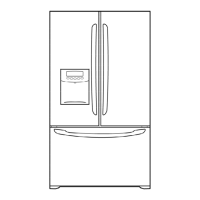
| Category | Refrigerator |
| Type | French Door |
| Ice Maker | Yes |
| Water Dispenser | Yes |
| Defrost Type | Frost-Free |
| Energy Star Certified | Yes |
| Color | Stainless Steel |
| Width | 35.75 inches |