EasyManua.ls Logo

Kenmore 795.7620 User Manual

Kenmore 795.7620
66 pages
To Next Page IconTo Next Page
Page #1 background imageLoading...
Page #1 background image
MODELS:
BOTTOM FREEZER REFRIGERATOR
REFRIGERATOR
SERVICE MANUAL
CAUTION
BEFORE SERVICING THE PRODUCT
READ THE SAFETY PRECAUTIONS IN THIS MANUAL.
Sears Brands Management Corporation, Hoffman Estates, IL 60179 U.S.A.
www.sears.com
color number
795.7620
795.6827
795.7827
Question and Answer IconNeed help?

Do you have a question about the Kenmore 795.7620 and is the answer not in the manual?

Kenmore 795.7620 Specifications

General IconGeneral
BrandKenmore
Model795.7620
CategoryRefrigerator
LanguageEnglish

Summary

Safety Precautions

Specifications

Disconnect Power Cord Before Servicing

Important safety instruction to disconnect power before servicing.

Disassembly

Reverse Drawer Refrigerator Door

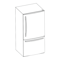
Detailed steps for reversing the refrigerator door for drawer type models.

Pull Out Drawer Removal

Instructions for removing the pull-out freezer drawer, requiring two people.

Reverse Swing Refrigerator and Freezer Doors

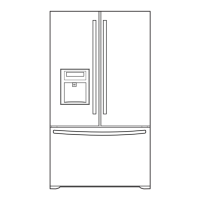
Detailed steps for reversing swing refrigerator and freezer doors.

Adjustment

OLP (Overload Protector)

Definition and role of the Overload Protector (OLP) in compressor protection.

Circuit Diagram

For Drawer Type Models

Circuit diagram for drawer type refrigerator models.

For Swing Type Models

Circuit diagram for swing type refrigerator models.

Troubleshooting

Compressor and Electric Components

Troubleshooting steps for compressor and related electrical components.

PTC and OLP

Diagnostic steps for PTC starter and Overload Protector (OLP).

Other Electrical Components

Troubleshooting for other electrical components like fan motors and heaters.

Service Diagnosis Chart

Chart for diagnosing common refrigerator complaints and their remedies.

Refrigeration Cycle

Troubleshooting chart related to refrigerant leaks, restrictions, and compression issues.

Sealed System Diagnosis

Diagnostic flow chart for sealed system issues causing no cooling.

Operation Principle and Repair Method of Icemaker

Circuit of Micom (Drawer Type Models)

8-2 PCB Function

8-3 Resistance Specification of Sensor

Circuit of Micom (Swing Type Models)

Defect Diagnosis Function

How to check and interpret error codes displayed on the panel.

Test Mode

Procedures for entering and operating various test modes for diagnostics.

9-2 PCB Function

9-3 Resistance Specification of Sensor

Related product manuals