12
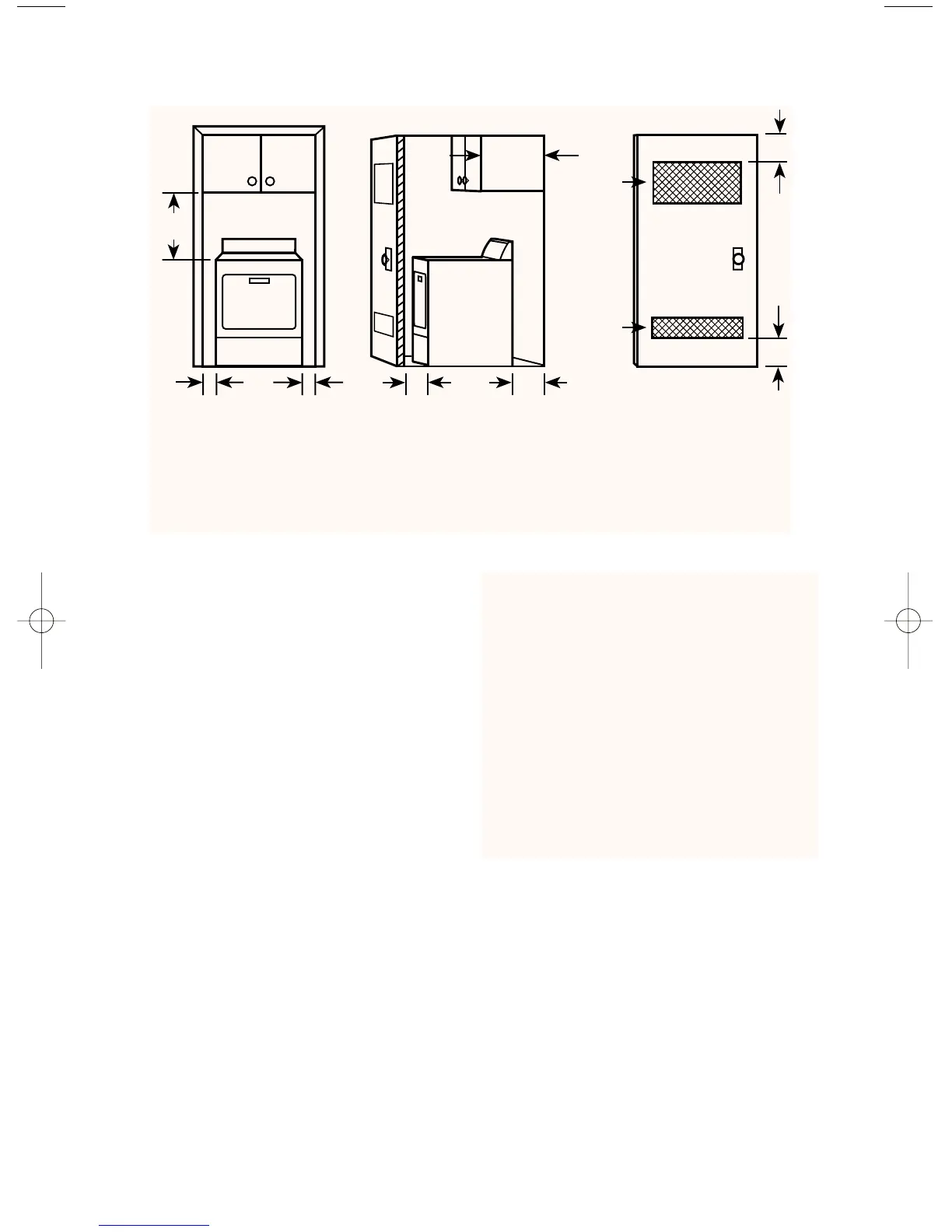
MINIMUM INSTALLATION SPACING
• In the above illustration, the installation
spacing is in inches and is the minimum
allowable.
• Additional spacing should be considered
for ease of installation and servicing.
***5
1
/2"
Front View
(Door With Vent)
Front View
(Door Not Shown)
Side View
(Door Shown)
* Additional clearances for wall, door and floor moldings may be required. 0" clearance
is acceptable but not recommended.
** Opening is minimum for closet door. Louvered door with equivalent air
openings is acceptable.
*** Additional space is needed when external exhaust elbow is used. Can be 0" clearance
when house exhausting is lined up directly with dryer exhaust.
27
3
/4"
*1"
1"
*1"
27"
18"
3"
3"
14" max.
**48 sq. in.
minimum
ventilation
area
**24 sq. in.
minimum
ventilation
area
• If closet door is installed, the minimum
air openings in top and bottom are
required. Louvered doors with equiva-
lent air openings in top and bottom are
acceptable.
• All installations must be exhausted
outside. Use at least the minimum
dimensions indicated.
28
3
⁄8"
8318111(v04) 3/3/00 9:56 AM Page 12