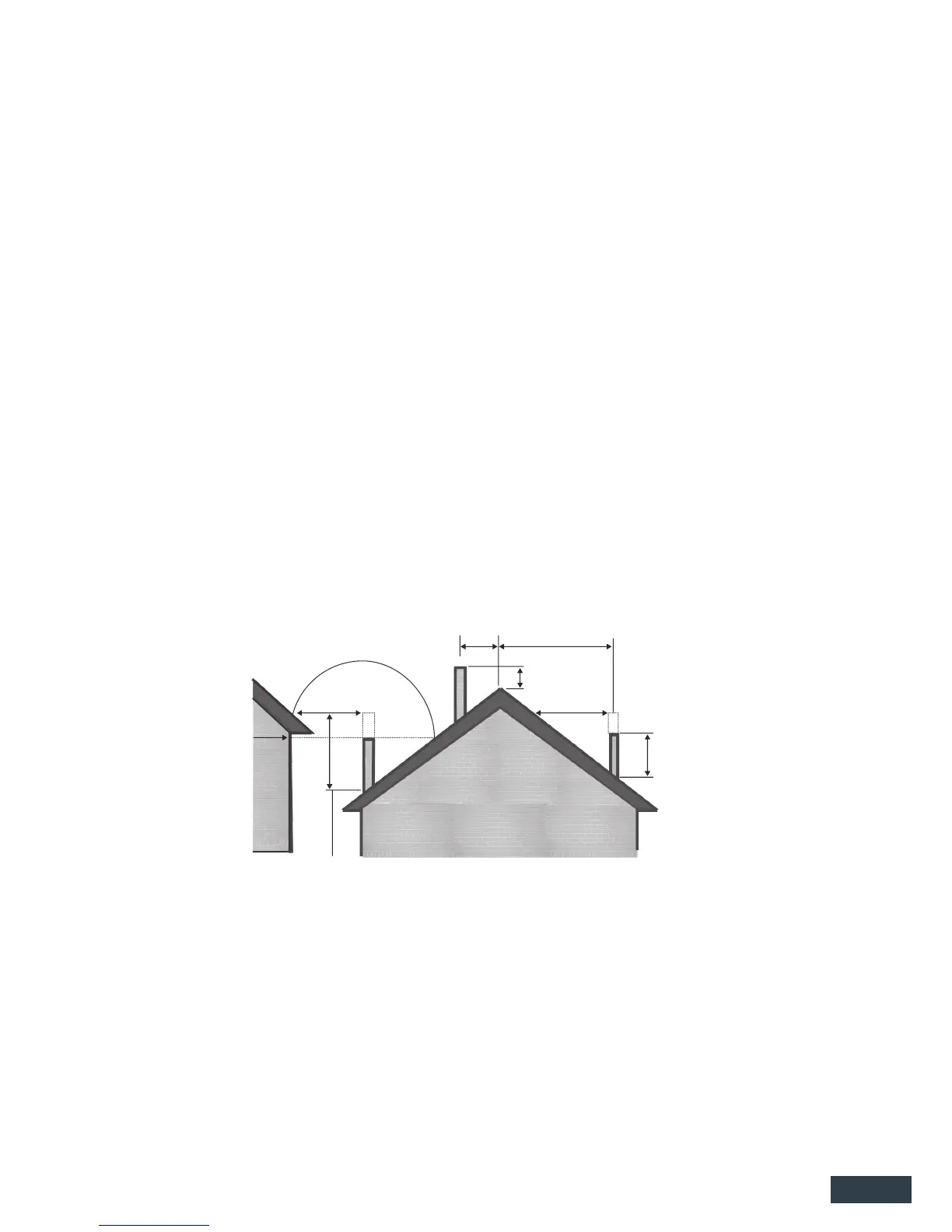
No part of a building, or any adjacent object, may be above the ue in a circular area of 3
metres from the ue exit.
These heights are given as a minimum, and in actual practice the presence of surrounding
structures, trees, fences, etc. may necessitate additional ue height for satisfactory
performance.
5
INSERT FLUE INSTALLATION
Determine whether the ue pipe will t vertically in the chimney from the heater to the cowl. An
adjustable bend may be required to offset the ue from the heater in order to clear part of the
chimney structure. If an offset is required, it should be tted to the ue outlet on the heater, so
that the ue pipe itself is vertical. The ue pipe should not touch the masonry.
Check chimney for accepting ue is in sound condition, and xing of outer casing or chimney
cap ashing to chimney crest is achievable.
3m
3m
3m More than 3m
0.6m
1m min
or less
Increase as
necessary
until nothing
is within 3m of
top of ue
FIG. 2
Increase from
1m until clear
within 3m of
top of ue
additional 200mm sections of ue as necessary to ensure minimum 1m ue height above roof is
achieved (Refer Fig.2 for more detail). Ensure the 150mm ue pipe extends at least 180mm above
the 200mm ue casing at the top. Trim ues if required.
Join together as many 250mm outer ue casings as manageable with swaged ends up, x
lengths together with 3 rivets or self-tapping screws and slide over 200mm ue casing pipe from
the top down to sit in position onto the 250mm section of ue transition atop the Zero clearance
box. Add additional 250mm sections of ue as necessary to nish at the same height as the
200mm ue liner. Trim last section if necessary.
Fit a suitable ashing over the ue and roof penetration hole to ash the outer casing to the
roof, seal and x ashing to roof and outer liner casing with an appropriate waterproof seal.
Place top spreader bracket in place and tighten, slide the cowl transition over the 150mm ue
pipe until it rests on the top spreader, t the Rain-Hat cowl. Note; Rain-Hat must be removable for
cleaning. In high wind zones secure in place with a self tapper screw.
Where a ue terminates more than one full ue section above the roof penetration, it must be
restrained with guy wires or support bracing bars for stability in high wind conditions.
The ue system should be vertical and without bends. If an offset is required, it should be as close
to the wood re as practicable and should not be offset more than 500mm from the centre line
of the ue stub. Clearances from the ue pipe to combustible materials must be maintained.
Restrictions or leaks in the ue system may reduce the draught, and, in severe conditions, could
cause smoke to enter the room.
NOTE: The ue pipe shall extend not less than 4.6m above the top of the oor protector.
The ue cowl must be at least 0.6m above the highest point of the roof, if within 3 metres of the
ridge. The ue cowl must be at least 1m above the roof penetration if more than 3 metres from
the ridge (Refer Fig. 2).
 Loading...