6
DOOR HANDLE AND DOOR
The door handle is pre-tted and should not require
any adjustment on assembly of the re.
To ensure the door is shutting correctly cut a plain
piece of paper about 50mm wide and place between
the open door and the door frame. Close the door
and try to pull the paper out. If the paper can be
freely pulled out, the door will need to be adjusted
so when the door and handle is in the locked closed
position pressure is applied to the paper strip ensuring
door seal is seated correctly.
If the handle has too much sideways movement the back nut on the hinge screw will need
to be released. Tighten the hinge screw with an Allen key until the desired movement is
achieved (not too tight, not too loose), then re-tighten back nut to hold screw in position.
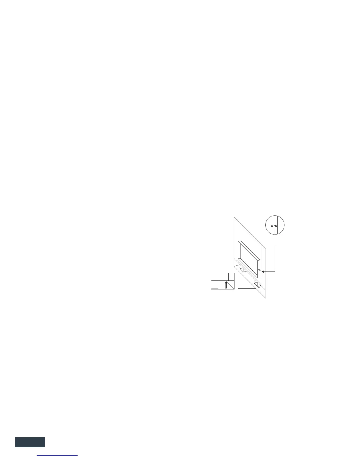
Any adjustment required to maintain the correct t of the door is made at the door catch pin
on the right side of the door lip. To adjust the t of the door catch, loosen the lock nut and turn
the catch pin to loosen or tighten the t. Re-tighten the lock nut (Refer Fig 3).
TOPOGRAPHY OF THE LAND
Given that the Topography of the land and atmospheric conditions vary considerably from house
to house, it is possible for a wood re ue to comply with the minimum requirements set out in g.
2 but still fail to extend upward far enough to establish ambient updraft. It is not uncommon for
replaces in houses that are surrounded by hills or trees, or that are located by large bodies of
water to need more ue height than the minimum required by code.
Seismic resistant
bolt location
Door adjustment
catch pin
FIG. 3
Install the selected Kent wood burner into the prepared replace. Once in position and level x
the re to the base of the replace enclosure with suitable anchors through the supplied xing
points in the base of the wood burners outer box.
Determine the total length of ue pipe and outer casing required by measurement.
Assemble the ue pipe lengths with the swaged ends of the upper section inside the plain ends
of the lower pieces. Drill and x each length with three stainless rivet’s or self-tapping screws. This
may be done on the ground and then the whole assembled length lowered down the chimney
to sit in the re spigot. Note: It is important that each ue joint is sealed with commercially
available ue sealing compound, including the joint between ue spigot and the rst length of
ue pipe.
Locate the ue or adjustable bend into the ue outlet of the heater and ensure ue pipe or
bend is sealed into re spigot with ue sealant.
Ensure the top of the chimney terminates at a point complying with the guidelines noted in g.
2 and that the ue pipe extends above the 250mm casing ue by 180mm. Trim ues as required.
Secure the top spacer bracket to the ue pipe and ensure the slots t snugly inside the 250mm
chimney liner.
Secure outer liner to chimney cap ashing, or cement outer liner in position with mortar or other
suitable sealing compound ensuring that there are no gaps and a water tight seal is achieved.
Note: some areas require a chimney cap ashing to be used (not supplied).
Slide the cowl transition over the ue pipe until it rests on the top spreader. Fit and secure rain hat
or cowl noting it must be readily removable for ue sweeping.
 Loading...