A
E
B
A
C*
A
D
INBUILT FLUE INSTALLATION
Once zero clearance box and 600mm ue transition is in desired place. Plumb up and cut a
260mm square penetration for the passage of the ue pipe and casing through the ceiling. If
preferred there can be no ceiling in the framed enclosure. Cut an opening through the roof
to position the outer casing through the roof and connect into ue starter transition. Support if
necessary with metal bracing angle to suitable anchorage points.
Join the required number of 150mm ue pipes by inserting the swaged ends of the upper piece
into the plain end of the lower piece. Drill and x each length with three stainless rivets or self-
tapping screws. It is important that each 150mm ue pipe joint is sealed with commercially
available ue sealing compound, including the joint between the re spigot and the rst length
of ue pipe.
Assemble as many 200mm inner ue casings together as manageable with swaged ends up, x
lengths together with 3 rivets or self-tapping screws and slide over 150mm ue pipe from the top
down to sit in position onto 200mm section of ue transition atop the Zero clearance box. Add
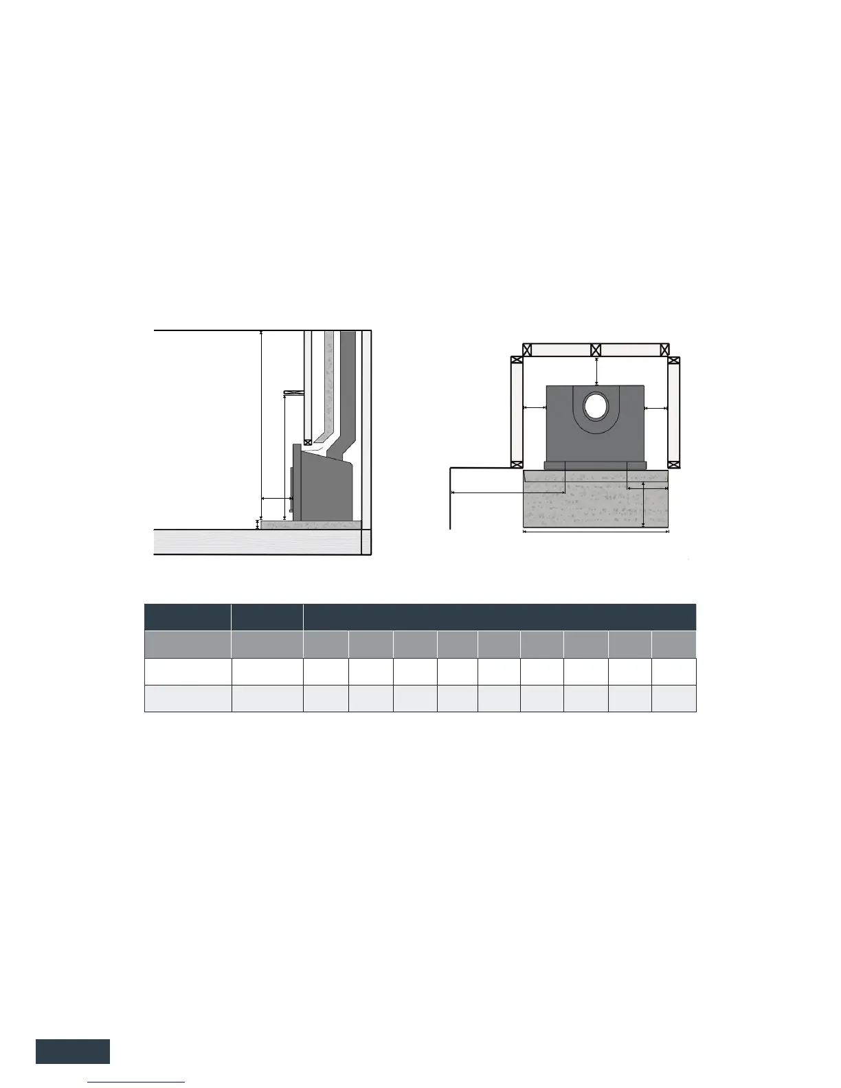
Minimum Installation Clearances (mm)
Model Model No. A B C* D E F G H I
Rata KWF295-6938 25 500 300 200 840 59 2000 1200 160
Logfire II KWF295-6937 25 500 300 200 840 59 2000 1200 160
* Floor protector from front of fascia.
TABLE 2
Inbuilt InstallationInsert installation
FIG. 1
I
G
H
C*
F
A
Plan ElevationSide Elevation
(Masonry Cavity) (Timber Cavity)
4
Open the door of the re and manoeuvre the fascia over the open door taking care not to
scratch the paint on the door. Align holes in fascia with screw locater holes in outer cabinet.
Close the re door and secure fascia to re outer cabinet with screws and washers supplied.
Check that door is central in fascia opening and tighten screws once fascia is in the desired
position.
Ret louvers by placing in position at a 45° angle into the louver opening. Place the rst louver
bar at the top behind the front of the fascia. Rotate louver into position and pull down to locate
bottom pins in position.