SPECIFICATIONS
INBUILT & INSERT WOOD FIRE INSTALLATION
To install an above Kent Wood Fire ensure the following required items are available; the
correct assembled Wood Fire and Fascia, an adequate oor protector, a zero clearance box
if required, the correct ue components and a suitable ashing system for the roof penetration
or chimney top to local Council requirements.
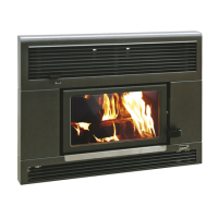
INBUILT FIRE INSTALLATION (TIMBER CONSTRUCTION)
The Kent inbuilt re requires a zero clearance box when installed into a timber cavity. A oor
protector or hearth must be used. The oor protector must extend under the wood re and not
less than 300mm in front of the fuel-loading and ash removal opening. The width of the oor
protector should not be less than the width of the wood re fascia.
Place the wood re into the desired position and plumb for the ceiling and roof penetrations.
Position the wood re to allow for the Kent triple skin ue systems 250mm outer casing to have
a clear path through the roof. Check the proposed route of the ue to ensure it is clear of roof
trusses and rafters in the ceiling space or other obstructions. An inbuilt re must be installed in
conjunction with the Kent KWF298-7374 triple skin ue kit and instructions which are included
with the ue kit.
See page 8 for more information on zero clearance box installation.
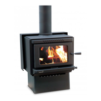
INSERT FIRE INSTALLATION (MASONRY CONSTRUCTION)
Prepare the masonry replace to accept the selected insert wood re and ue ensuring
installation requirements for width, depth and height measurements are acceptable for the
wood re to t into the replace (Refer to Table 1). Determine whether the ue pipe will t
vertically in the chimney from the heater to the cowl or if an offset is required in the ue. Install
the selected Kent wood re into the prepared replace. Once in position and level, x the re
to the base of the replace enclosure with suitable anchors. An insert re must be installed
in conjunction with the Kent KWF298-6025 standard inset ue kit and instructions which are
included with the ue kit.
The wood re must be restrained against movement in the event of an earthquake. Ensure the
Kent wood re is restrained by xing the wood re to the oor protector with two bolts of 6mm
minimum diameter through the holes provided in the outer box base. For solid concrete oors,
use 8mm DYNABOLTS
®
or similar, with a minimum depth of engagement into the oor of 50mm.
INSTALLING THE FASCIA
Unpack the fascia. And remove the top and bottom louvers by lifting the louver up and then
rotating it out from the bottom.
Unpack screws and screw locator’s from supplied bag. Fit screw locator’s to steel re box
clipping them over precut holes in outer box.
External re dimensions (mm)
Model Model No. Width Depth Height
Average
emissions
Average
efciency
Rata KWF295-6938 560 520 554 0.51g/kg 69%
Logfire II KWF295-6937 560 520 554 0.51g/kg 69%
TABLE 1
3