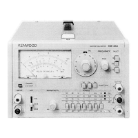
DM-81
DIP METER
INTRODUCTION .............................................................................................................. 1
Inductive coupling (Fig. 1A)........................................................................................... 1
Capacitive coupling (Fig. 1B)......................................................................................... 1
FEATURES ........................................................................................................................ 3
SPECIFICATIONS............................................................................................................. 4
CONTROLS ....................................................................................................................... 5
PRECAUTIONS................................................................................................................. 6
Battery and Oscillation Coil Loading ............................................................................. 6
Obtaining a Dip Point ..................................................................................................... 6
Measuring Transistor Resonant Circuits......................................................................... 6
Caution in Measuring Transmitters ................................................................................ 6
Caution in Motor Pointer Deflection Change................................................................. 7
APPLICATIONS................................................................................................................ 7
Use as a Dip Meter.......................................................................................................... 7
Other Frequency Measurements ..................................................................................... 8
Resonant circuit measurement.................................................................................... 8
Use of the capacitive probe......................................................................................... 8
Antenna resonant frequency measurement............................................................... 10
Use as a Signal Generator......................................................................................... 11
Use as Crystal Checker and Marker Generator......................................................... 11
Use as an Absorption Frequency Meter.................................................................... 12
Use as a Field-Strength Meter................................................................................... 13
Capacitance and Inductance Measurements ............................................................. 14
ADJUSTMENT ................................................................................................................ 17
VR1: 01 Bias adj........................................................................................................... 17
VR2: Meter zero adj...................................................................................................... 17
VR3: Sensitivity adj...................................................................................................... 17
VR4: Battery voltage check adj.................................................................................... 17
PARTS AND SERVICE................................................................................................... 17
Ordering Spare Parts..................................................................................................... 17
Service........................................................................................................................... 17
PARTS LIST..................................................................................................................... 18
PRINTED CIRCUIT BOARDS ....................................................................................... 22
SCHEMATIC DIAGRAM ............................................................................................... 24