Do you have a question about the Kenwood VT-171 and is the answer not in the manual?
Describes high reliability and good saturation restoration from input amplifiers.
Mentions high sensitivity and reliability of the meter.
States high input resistance (10M\[03A9\]) and low parallel capacitance.
Explains scales for RMS, dB, and dBm values for relative measurements.
Lists measurable AC voltage ranges and scales.
Outlines the frequency response characteristics and references.
States the input impedance and parallel capacitance.
Lists maximum durable input voltages for different ranges.
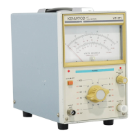
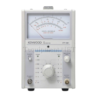
Describes controls and indicators on the front panel.
Details controls and connectors on the rear panel.
Explains preset trimmer/resistor controls on the side panel.
Step-by-step guide for setting up the voltmeter before use.
Explains the two voltage scales and their readings.
Describes the dB scale, its reference, and reading methods.
Explains measuring amplifier gain using a signal generator.
Steps for removing the device casing using a screwdriver.
Steps for mounting the device casing correctly.
Procedure for replacing blown fuses and voltage selection.
Adjust meter zero-adjust screw before powering on.
Connects calibrator and sets voltage for adjustment.
Adjusts VR102 for full scale pointer swing.
Adjusts VR101 for full scale pointer swing.
Covers warm-up, environmental factors, and noise.
Recommends input cables and specifies maximum input voltage.
Advises on storage conditions and power cord safety.
| Brand | Kenwood |
|---|---|
| Model | VT-171 |
| Category | Measuring Instruments |
| Language | English |