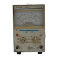
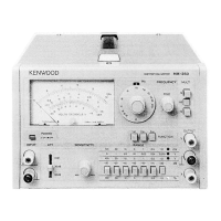
The Kenwood VT-175 is a 2-channel AC voltmeter, presented as a dual-channel electronic voltmeter set housed in a single cabinet. It features two independent AC voltmeters with a two-pointer meter for easy dual measurements and inter-channel comparisons. The VT-175 is designed as a wideband, high-sensitivity voltmeter suitable for various voltage measurements, and it can be used with a remote control unit.
Function Description:
The primary function of the VT-175 is to measure sinusoidal wave voltages as an AC voltmeter. It also supports a variety of applications, including amplifier gain measurement and voltage calculations for special waveforms. The device provides output signals by amplifying input signals such that the signal amplitude of a meter full-scale becomes 1 Vrms, regardless of the selected range.
Important Technical Specifications:
Meter Section:
- Measurable voltages: 1mV to 300V in 12 ranges (1mV, 3mV, 10mV, 30mV, 100mV, 300mV, 1V, 3V, 10V, 30V, 100V, and 300V full scales).
- dB range: -80 to +50dB (0dB=1V).
- dBm range: -80 to +52dBm (0dBm=1mW, 600Ω).
- Error: Within ±3% of full scale at 1kHz.
- Frequency response:
- ±10% at 5Hz to 1MHz
- ±5% at 10Hz to 500kHz
- ±3% at 20Hz to 200kHz
- ±2% at 30Hz to 100kHz (referenced to 1kHz response).
- Input impedance: 10MΩ ±5%, with less than 45pF parallel capacitance.
- Durable input voltage: 500V (DC+AC peak) at 1V to 300V range; 100V (DC+AC peak) at 1mV to 300mV range.
- Stability: Within ±0.5% of full scale for ±10% line voltage fluctuation.
- Residual voltage: Less than 20μV with input shorted on 1mV range.
- Crosstalk, Individual: Less than -80dB with other input terminated with 600Ω.
- Interlock: Less than -50dB with other input terminated with 600Ω.
Amplifier Section:
- Gain: Approx. 60dB.
- Output voltage: 1Vrms (Full scale) ±20%.
- Output impedance: 600Ω ±20%.
- Distortion: Less than 1% at full scale (rated by signal-to-noise ratio in 1mV and 1V ranges).
- Signal-to-noise ratio: Over 40dB at full scale.
- Frequency response: Within ±3dB at 5Hz to 500kHz.
Environmental:
- Coefficient: ±0.08%/°C.
- Temperature (within specification): 10 to 40°C.
- Temperature (full operation): 0 to 50°C.
- Relative humidity: Less than 80%.
Power Supply Section:
- Line voltage: 100, 120, 220V AC ±10%; 216-250V AC, 50/60Hz.
- Power consumption: Approx. 7W.
Physical Specifications:
- Dimensions: W x 190 (212) H x 238 (268) Dmm (values in parentheses include protrusions).
- Net weight: 3 kg.
Usage Features:
- Dual-channel measurement: The VT-175 allows for simultaneous measurements on two channels, CH1 and CH2, with a two-pointer meter for easy comparison.
- Remote control capability: The RT-61 option provides remote control functionality.
- Range selection: Ranges can be set individually for each channel or in an interlocked manner, where both CH1 and CH2 ranges are changed simultaneously.
- Ground mode selector: Allows floating the measuring circuit above ground (OPEN state) or connecting it to the casing's grounding terminal (GND state). The GND state is recommended for normal use.
- Voltage scales: Features two black voltage scales (0-10 and 0-3) for reading voltage values, with the ability to read down to -80dB (0.1mV) and up to +50dB (300V) by adjusting the range selector.
- dB and dBm scales: Provides scales for measuring dBV (referenced to 0dB=1V) and dBm (referenced to 0dBm=1mW across a 600Ω load).
- Output signals: CH1 and CH2 outputs provide amplified input signals, with a full-scale amplitude of 1Vrms, regardless of the selected range.
- Warm-up time: For accurate measurements, a warm-up period of approximately five minutes is recommended after turning on the device.
- Input cable requirements: Use low-capacitance shielded or coaxial cables. For higher audio frequencies, terminate input connectors with 50Ω or 600Ω resistors.
- High voltage measurement caution: Exercise full care when measuring high voltages, as the continuous maximum input voltage is 100V (DC+ACpeak) for ranges from -60dB to -10dB.
- Environmental considerations: Avoid placing the voltmeter in strong magnetic or electric fields, and do not store it in high temperature or humidity environments for extended periods.
- Power-off behavior: The ON/OFF switch controls the secondary side of the power transformer; the primary side remains energized. For long periods of disuse, unplug the power cord from the receptacle.
Maintenance Features:
- Fuse replacement: If a fuse blows, check for the cause, remedy it, and replace the fuse with a new one of the specified capacity (0.5A for 100V/120V AC, 0.3A for 220V/240V AC).
- Voltage changeover: The line voltage can be changed by adjusting the fuse holder on the rear panel and replacing the fuse with the appropriate capacity.
- Alignment: The voltmeter is factory-aligned but can be realigned if necessary. This involves adjusting preset controls (trimmer capacitor TC101, variable resistors VR101 and VR102) located on the main PC board on the right-hand side panel.
- Zero-adjust screws: Meter zero-adjust screws (right for CH1, left for CH2) on the front panel allow for precise zero calibration before operation.