EasyManua.ls Logo

Kenwood VT-173 - User Manual

Kenwood VT-173
16 pages
Print Icon
To Next Page IconTo Next Page
Loading...
KENWOOD
©PRINTED
II .PAN
AUTO RANGE VOLTMETER
VT-173
INSTRUCTION
MANUAL
KENWOOD CORPORATION
Question and Answer IconNeed help?

Do you have a question about the Kenwood VT-173 and is the answer not in the manual?

Overview

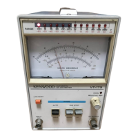
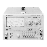
The KENWOOD Electronic Voltmeter VT-173 is an auto-range voltmeter designed for measuring AC voltage. It operates on the absolute-mean value indication principle, displaying readings on a root-mean-square value scale.

Function Description:

The VT-173 measures AC voltage across a wide frequency range from 10Hz to 1MHz. It features a broad full-scale range from 1mV to 300V. The device automatically selects the optimal measurement range based on the input level, though manual range selection is also possible. For production line applications, an optional remote control unit is available. The VT-173 can also function as a high-gain, wide-band amplifier through its output terminal. AC and DC outputs are provided for monitoring purposes.

Important Technical Specifications:

Meter Section:

  • Measurable Voltages: 1mV-300mV across 12 ranges (1mV, 3mV, 10mV, 30mV, 100mV, 300mV, 1V, 3V, 10V, 30V, 100V, and 300V full scales).
  • dB: -80~+50dB (0dB=1V).
  • dBm: -80~+52dBm (0dBm=1mW, 600Ω).
  • Error: Within ±3% of full scale at 1kHz.
  • Frequency Response:
    • ±10% at 10Hz-1MHz
    • ±3% at 20Hz-200kHz
    • ±2% at 50Hz-100kHz (referenced to 1kHz response).
  • Input Impedance: 10MΩ±5%, with less than 45pF parallel capacitance.
  • Durable Input Voltage:
    • 500V (DC+AC peak) for 1V to 300V range.
    • 100V (DC+AC peak) for 1mV to 300mV range.
  • Stability: Within ±0.5% of full scale for ±10% line voltage fluctuation.
  • Residual Voltage: Less than 20μV with input shorted on 1mV range.

AC Output Amplifier Section:

  • Output Voltage: 1Vrms ±20%.
  • Output Resistance: 600Ω ±20%.
  • Frequency Response: Within ±3dB at 10Hz-500kHz.
  • Distortion: Less than 1% at full scale (rated by signal-noise ratio in 1mV range).
  • Signal-to-Noise Ratio: Over 40dB at full scale.

DC Output Amplifier Section:

  • Output Voltage: 1V±20% + offset voltage at full scale.
  • Offset Voltage: ±100mV.
  • Output Resistance: 600Ω ±20%.
  • Ripple: Less than 10mVrms.
  • Frequency Response: Within ±3dB at 10Hz to 1MHz.

Environmental:

  • Temperature Coefficient: ±0.08%/℃.
  • Within Specifications Temperature: 10~40℃.
  • Full Operating Temperature: 0~50℃.
  • Relative Humidity: Less than 80%.

Power Supply Section:

  • Line Voltage: 100, 120, 220V AC ±10%, 216-250V AC, 50/60Hz.
  • Power Consumption: Approx. 5W.
  • Dimensions: 128(130) W × 190(215) H × 238(270) Dmm (values in parentheses include protrusions).
  • Net Weight: 3.2kg.

Usage Features:

  • Dual Power Differential Input Amplifiers: The entire circuit uses dual power differential input amplifiers, ensuring high reliability and good restoration characteristics from potential saturation due to excessive inputs.
  • Large Taut-band Meter: Equipped with a large, sensitive, and reliable Taut-band meter.
  • Minimized Adjusting Trimmers: The design minimizes the number of adjusting trimmers by using amplifiers with precisely calculated open-loop gains and negative biasing through 1% accurate metal-film resistors, ensuring stability against secular changes.
  • Meter Scales: The meter scales are graduated in root-mean-square values for sinusoidal waves. It also includes dB and dBm scales for convenient relative value measurements.
  • Auto Mode: The VT-173 automatically selects the measurement range where the meter pointer indicates a value from 27% to 102% of the full scale. If the input signal is between 85% and 102% of the full scale, a higher range can be selected to indicate the voltage within 27% to 32%, or the sensitivity can be increased by one range with the DOWN switch to indicate the voltage within 85% to 102%.
  • Hold Mode: Allows the user to fix the measurement range manually. The range immediately before setting the selector switch to HOLD position is maintained.
  • Relative Reference Control: The RELATIVE REF control can be set to "CAL" for absolute value readings or adjusted to "UNCAL" to set a desired reference level (e.g., 0dBm) for measuring relative levels like frequency responses.
  • Remote Control (Optional): The RT-61 option enables remote control of the VT-173's measurement ranges.
  • AC/DC Output Connectors: The AC OUTPUT connector provides 1Vrms AC voltage when the meter reads full scale, regardless of the measurement range. Similarly, the DC OUTPUT connector provides approximately 1V DC voltage when the meter reads full scale. Both have an output impedance of 600Ω.
  • Root-Mean-Square and Peak Value Calculations: The VT-173, as an absolute-mean value indication type voltmeter, reads RMS values for sinusoidal inputs. For non-sinusoidal waves, the HOLD (manual) mode should be used, and RMS and peak values can be calculated if the form factor and crest factor of the input wave are known.

Maintenance Features:

  • Casing Removal: The casing can be removed by unscrewing six screws on the sides and top, then widening the bottom of the 7-shaped casing and pulling it up.
  • Casing Mounting: When remounting, widen the bottom of the casing, fit the PC board retainer, and alternately tighten the six screws for uniform torque.
  • Fuse Replacement: If a fuse blows, check for the cause, remedy it, then remove the fuse holder cap on the rear panel with a minus screwdriver, replace the fuse with a new one of the correct capacity (0.2A for 100V/120V AC, 0.1A for 220V/240V AC).
  • Supply Voltage Change: The fuse holder on the rear panel can be adjusted to select the preferred voltage indication (100V, 120V, 220V, or 240V). Changing from 100V/120V to 220V/240V requires changing the fuse from 0.2A to 0.1A.
  • Alignment: The VT-173 is factory-adjusted but can be realigned if necessary. This involves adjusting the meter pointer to zero, setting the MODE selector to HOLD, connecting a voltmeter calibrator, and adjusting VR102 and VR101 for full-scale readings at specific voltages (300mV, 3V). Further adjustments involve using a wide-band signal generator and controlling RELATIVE REF, VR201, and VR202 to ensure accurate range switching and readings at various mV levels.

Cautions for Use:

  • Warm-up Time: Allow approximately five minutes for warm-up after pressing the POWER switch for accurate measurements.
  • Environmental Conditions: Avoid placing the VT-173 in areas with strong magnetic or electric fields. Do not leave it in high temperature or humidity for extended periods.
  • Input Cable: Use a low-capacitance shielded cord or coaxial cable for input, other than the supplied one.
  • Maximum Input Voltage: The maximum allowable continuous input voltage is 100V (DC + AC peak) when the measurement range is set to 1mV~300mV. Exercise caution.
  • Noise Sensitivity: The VT-173 is a highly sensitive voltmeter, so be aware of line noises or other low-level noises. Use great care when connecting a long cable or an instrument with poor isolation to the MONITOR OUT connector.
  • Non-Sinusoidal Waves: For measuring non-sinusoidal wave voltage, be sure to use the HOLD (manual) mode.
  • Power Cord Disconnection: The ON/OFF switch acts on the secondary side of the power transformer, meaning the primary side remains energized even when the unit is OFF. For long periods of disuse, unplug the power cord from the receptacle outlet.

Kenwood VT-173 Specifications

General IconGeneral
BrandKenwood
ModelVT-173
CategoryMeasuring Instruments
LanguageEnglish

Related product manuals