Do you have a question about the Kenwood VT-181 and is the answer not in the manual?
Procedure for calibrating the 300mV range, including input signal and waveform checks.
Procedure for calibrating the 1V range with signal input and pointer verification.
Procedure for adjusting the unit to maintain accuracy at 100 kHz.
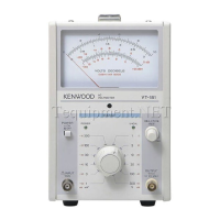
| Brand | Kenwood |
|---|---|
| Model | VT-181 |
| Category | Measuring Instruments |
| Language | English |