Do you have a question about the Kenwood DNX5220 and is the answer not in the manual?
| Auto | Yes |
|---|---|
| Marine (chartplotters, sounders) | No |
| Map view options | 2D/3D |
| I/O ports | 1 x AV(mini-jack), 1 x RCA AV, 1 x RCA Video |
| GPS receiver | SIRF3 |
| Power requirements | 14.4V, 15 A |
| Form factor | Fixed |
| Product color | Black |
| Display resolution | 336960 pixels |
| Display size (HxV) (imperial) | 6.1 \ |
| USB 2.0 ports quantity | 1 |
| Audio formats supported | AAC, MP3, WMA |
| Video formats supported | DivX |
| Storage temperature (T-T) | -20 - 85 °C |
| Operating temperature (T-T) | -10 - 60 °C |
| Depth | 158 mm |
|---|---|
| Width | 182 mm |
| Height | 112 mm |
| Weight | 1900 g |
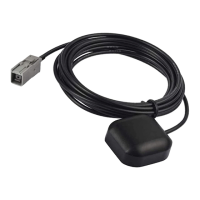
Process for obtaining satellite signals for the first time when turning on the system.
Standard connection where A-7 is ignition and A-4 is constant power.
Connection where A-7 is constant power and A-4 is ignition.
Connection where A-4 is unused and A-7 is constant power.