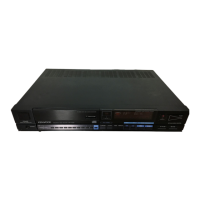
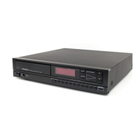
Do you have a question about the Kenwood DP-1100 B and is the answer not in the manual?
Explains the focus servo's role in maintaining the laser spot on the disc surface.
Describes the tracking servo's function to follow the disc's signal track.
Details the CLV servo's function in maintaining constant linear velocity.
Explains the detection methods for focus and tracking errors.
Details focus error detection using critical angle prism and reflection ratio.
Explains tracking error detection using the heterodyne system.
Explains how the focus servo loop maintains focus on the disc.
Describes the tracking servo's function to follow the disc's signal track.
Explains the power-on and power-off reset sequence.
Details the process of searching for the correct focus point.
Describes disc detection and prevention of reverse motor rotation.
Details the focus servo operation including feedback and compensation.
Explains tracking servo operation, including error signal processing.
Describes generation of tracking error and kick operation control.
Explains control signals for focus servo operation.
Explains dropout detection and PUFF/KICK operations.
Details the TMP4740N main microprocessor IC.
Describes the MB88201 SVC microprocessor IC.
Details the TMP47C41N display microprocessor IC.
Describes the flowchart for closing the disc tray.
Explains how disc presence is detected using DOK and FSRCH signals.
Describes the flowchart for judging disc surface/rear condition.
Explains fast forward/backward pickup operations.
Details dynamic and kick search systems for locating music.
Explains the pause operation using the search system.
Flowchart for checking initial power-on and operation status.
Troubleshooting guide for focus servo issues.
Troubleshooting guide for tracking servo problems.
Troubleshooting steps for the pickup feed motor circuit.
Troubleshooting for dropout control circuit, especially with scratched discs.
Troubleshooting for kick circuit operations and related signals.
Troubleshooting steps for tray mechanism issues.
Troubleshooting guide for CLV operation issues.
Troubleshooting for bit synchronization problems.
Troubleshooting for signal processing circuits.
Troubleshooting steps for D/A converter issues like distortion or no sound.
Troubleshooting for the display PCB and its components.
Explains how the pickup moves linearly via gears and rack.
Explains tray eject/load sequence when power is on.
Explains how the tray operates during disc loading and ejection.
Provides instructions for replacing major components.
Step-by-step guide for replacing the laser pickup assembly.
Instructions for replacing the disc motor and FG PCB.
Procedure for replacing the pickup carry motor.
Instructions for replacing the loading motor and gears.
Procedure for removing the head amplifier PCB.
Instructions for replacing the clamper lever mount.
Step-by-step guide for replacing the disc tray.
Details adjustment procedures for the clamper lever height.
| frequency response | 2 Hz to 20 kHz, ± 0.5 dB |
|---|---|
| dynamic range | 95 dB or more |
| signal-to-noise ratio | 95 dB or more |
| power supply | AC 120 V, 60 Hz |
|---|---|
| power consumption | 20 W |
| dimensions | 440(W) X 88(H) X 310(D) mm |
|---|---|
| weight | 6.8 kg |
| wow and flutter | Below measurable limit |
| frequency response | 2 Hz to 20 kHz, ± 0.5 dB |
|---|---|
| dynamic range | 95 dB |
| signal-to-noise ratio | 95 dB |
| power supply | AC 120 V to AC 220/240 V, 50/60 Hz |
|---|---|
| power consumption | 23 W |
| dimensions | 440(W) X 88(H) X 310(D) mm |
|---|---|
| weight | 6.8 kg |
| wow and flutter | Below measurable limit |