Do you have a question about the Kenwood DP-MA5 and is the answer not in the manual?
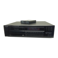
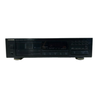
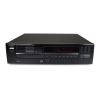
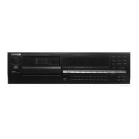
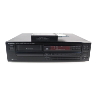
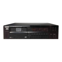
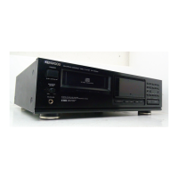
Identifies front panel parts including metallic cabinet, front glass, and display.
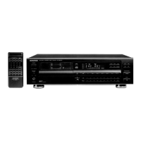
Details rear panel parts like panels, cord connectors, and feet.
Describes front panel buttons, indicators, and display elements for player operation.
Instructions for safely moving and transporting the CD player unit.
Explains the functions of the RC-A5 remote control for the DP-MA5 player.
Details RC-A7 remote control functions, including A/B selector switch operations.
Step-by-step guide for disassembling the MD mechanism deck, removing key components.
Instructions for replacing the optical pickup unit, including rod and screw removal.
Procedure for removing the Plus 1 tray assembly, involving screws and a lock lever.
Illustrates the interconnection of major ICs and functional blocks within the player.
Explains how to set and use test modes for diagnostics and adjustments.
Details the pin assignments and functions of the main µPD75217GF-616 microprocessor.
Describes the CXA1571M RF amplifier IC, its block diagram, and pin functions.
Explains the CXA1372Q servo processor, its functions, block diagram, and pin details.
Details the CXD2500AQ DSP IC, its functions, block diagram, and pin assignments.
Covers the TC9237BF D/A converter IC, including terminal connections and block diagram.
Procedures for adjusting tracking and focus error balance using test discs and oscilloscopes.
Steps for setting focus gain and tracking gain using test signals and AC voltmeters.
Illustrates reference waveforms for RF signal, tracking error, and focus error during adjustment.
Diagram showing the component layout on the main PC board for reference.
Highlights specific connection points on the PCB for calibration and adjustment procedures.
Exploded view illustrating the parts and their arrangement in the CD mechanism deck.
Exploded view showing the parts and their assembly within the main player unit.
Lists components for the mechanism deck and main unit, including part numbers and descriptions.
Details capacitor types, values, tolerances, and resistor codes for component selection.
Lists key performance metrics like laser type, rotation speed, frequency response, and SNR.
Provides the physical size (W x H x D) and net weight of the CD player unit.
| Type | CD Player |
|---|---|
| Weight | 7.5kg |
| Channels | 2 (stereo) |
| Output Level | 2V (fixed) |
| Disc Capacity | 5 |