EasyManua.ls Logo

Kenwood DVR-6100K User Manual

Kenwood DVR-6100K
35 pages
To Next Page IconTo Next Page
Page #1 background imageLoading...
Page #1 background image
note: This manual is not available for U.S.A and canada market.
DVD / AV RECEIVER
DVR-6100/6100K
SERVICE MANUAL
(DVT-6100)
© 2002-7 PRINTED IN KOREA
B51-5803-00 (K/K) 2196
MENU
STOP PLAY/PAUSE
INPUT
76
0
ON SCREENVOLUME
OPEN/CLOSE
POWER
-ON/OFFSTANDBY
ACTIVE EQ
ENTER
MIC LEVEL
CS II
TOP MENU/BAND
DSP
PRO LOGIC IIDOLBY DIGITAL
DTS
PHONES
(OPTICAL)
VIDEO AUDIO RL
FRONT AUX
DIGITAL
DEC cabinet *
(B07-)
DEC crystal
(B10-3900-08)
Con DIN socket
(E63-1243-08)
Con phono socket
(E63-1290-08)
Con phono socket
(E63-121-08)
Pun cover
(A01-3863-08)
In compliance with Federal Regulations, following are repro-
duction of labels on, or inside the product relating to laser
product safety.
KENWOOD Corp. certifies this equipment conforms to DHHS
Regulations No.21 CFR 1040. 10, Chapter 1, subchapter J.
DANGER : Laser radiation when open and interlock defeated.
AVOID DIRECT EXPOSURE TO BEAM.
Caution : No connection of ground line if disassemble
the unit. Please connect the ground line on
rear panel, PCBs, Chassis and some others.
DEC button
(K29-8255-08)
DEC button
(K29-8256-08)
DEC button
(K29-8251-08)
DEC button
(K29-8250-08)
Tuner ass'y *
(W02-)
MLD clamp
(J42-0350-08)
D-REM
(W02-2911-08)
Con phono socket
(E63-1244-08)
Conn-speaker
(E70-0165-08)
Con phono socket
(E63-1270-08)
DEC button
(K29-8254-08)
Phone jack
(E11-0957-08)
MLD indicator
(B10-3897-08)
IC-opt
(W02-2961-08)
DEC knob
(K29-8249-08)
DEC button
(K29-8253-08)
Con phono socket
(E63-1289-08)
Wire-MCRDM *
(E30-)
Illustration is DVR-6100K.
* Refer to parts list on page 37.
70%
Question and Answer IconNeed help?

Do you have a question about the Kenwood DVR-6100K and is the answer not in the manual?

Kenwood DVR-6100K Specifications

General IconGeneral
BrandKenwood
ModelDVR-6100K
CategoryReceiver
LanguageEnglish

Summary

Product Overview and Identification

Front Panel Components

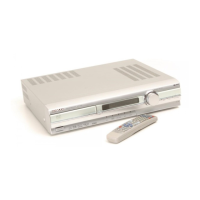
Identifies front panel buttons, indicators, and connectors.

Manual Structure and Safety Information

Table of Contents and Section Overview

Lists manual sections and topics covered.

Operational Cautions and Warnings

Provides guidance on condensation, operation, and safety notices.

Disassembly and System Configuration

Tray Opening Procedure

Details the method for opening the disc tray if it fails to eject normally.

System Block Diagram

Overall System Architecture

Illustrates functional blocks and interconnections of the DVR-6100/6100K system.

Circuit Description - MPEG Processor

MPEG Processor IC (IC61) Pinout

Explains pin functions and descriptions for the main MPEG processor IC.

Circuit Description - Memory and Interface

SDRAM, ADC, and Interface IC Pins

Details pin functions for SDRAM, ADC, and various interface ICs.

Circuit Description - Communication and Control

Communication Interfaces and Microcomputer

Describes pin functions for communication interfaces and the system microcomputer.

Circuit Description - Audio Processing

DSP, DAC, Tuner, and Control ICs

Explains pin functions for DSP, DAC, tuner, and control ICs.

Circuit Description - SDRAM and DAC

SDRAM and Stereo DAC IC Details

Details pin functions and descriptions for SDRAM and stereo DAC ICs.

Circuit Description - Memory and Drivers

Flash Memory, Inverter, and Driver ICs

Describes pin functions for flash memory, inverter, and driver ICs.

Circuit Description - Audio Input and Volume

Stereo Audio ADC and Volume Control ICs

Explains pin functions for stereo audio ADC and volume control ICs.

Circuit Description - Amplifiers and Converters

Power Amplifier and ADC/DAC ICs

Details pin functions for power amplifier and ADC/DAC ICs.

Circuit Description - Digital Audio and Registers

Digital Audio Decoder and Shift Register

Explains pin functions for digital audio decoder and details shift register diagram.

Wiring Diagram

System Interconnections

Illustrates wiring connections between internal boards and external connectors.

PC Board Layouts - DSP Board

DSP Board Component Placement

Shows component placement on the DSP board's sides.

PC Board Layouts - DVD Board

DVD Board Component Placement

Displays component placement on the DVD board's sides.

PC Board Layouts - Various Boards

Front, Switch, u-COM, and Power Boards

Shows component placement on multiple internal boards.

PC Board Layouts - Main Board

Main Board Component Layout

Displays component placement on the main board.

PC Board Layouts - u-COM Board

u-COM Board Component Layout

Shows component placement on the u-COM board.

Schematic Diagrams - Overview

Schematic Overview and Cautions

Provides schematic overview with ICs and general safety cautions.

Schematic Diagrams - Detail

Detailed IC and Board Connections

Illustrates detailed connections for ICs and boards.

Schematic Diagrams - Power and Selector

Power and Selector Board Schematics

Shows schematic details for power and selector boards, including destinations.

Exploded View

Unit Assembly Diagram

Provides a visual breakdown of unit components and assembly.

Parts List - Accessories and Cabinet

Accessory and Cabinet Parts

Lists part numbers for accessories and cabinet components.

Parts List - Main PCB

Main PCB Components

Lists part numbers for main PCB components.

Parts List - Resistors and Diodes

Resistors and Diodes

Lists part numbers for resistors and diodes.

Parts List - Other Components

Miscellaneous Components

Lists part numbers for additional resistors, ICs, and PCBs.

Parts List - Capacitors and ICs

Capacitors and ICs

Lists part numbers for capacitors and ICs.

Parts List - DSP PCB Components

DSP PCB Capacitors and ICs

Lists part numbers for DSP PCB capacitors and ICs.

Parts List - DVD PCB Components

DVD PCB Resistors and ICs

Lists part numbers for DVD PCB resistors and ICs.

Technical Specifications

Amplifier and Tuner Specs

Details power output, impedance, sensitivity, and tuner frequency ranges.

Player and Audio Specs

Lists specs for CD/Video CD player, digital and analog audio.

Exploded View - Assembly Details

Unit Assembly Diagram

Provides further details on unit assembly with an exploded view and part references.

Related product manuals