The KENWOOD FG-272 is a Function Generator that also functions as a pulse generator and sweep oscillator.
Function Description
The FG-272 provides a wide range of oscillation frequencies, from 0.2 Hz to 2 MHz, across seven selectable ranges (1/10/100/1k/10k/100k/1M). It offers selectable output waveforms including sine waves, square waves, and triangle waves through one-touch operation. A dedicated TTL square wave output connector allows for easy use of TTL-level square waves as a signal source for digital circuit experiments.
A key feature is the Symmetry Function, which allows for varying the symmetry of saw-tooth waves and pulse waves, and also enables inversion of the wave polarity. External sweep and output frequency control can be implemented by applying a voltage from 0 to +10V to the VCF IN connector. The linear sweep function provides sweep frequency control up to a maximum ratio of 100:1, with sweep frequency variable from 0.5 Hz (2 seconds) to 50 Hz (20 milliseconds). DC voltage (0 to ±10V) can be overlaid upon the output waveform. The device also features an ATT -20 dB pushbutton and a continuous attenuator, providing a maximum attenuation of over 40 dB. Its compact and lightweight design includes a convenient carrying handle that doubles as a tilting stand.
Important Technical Specifications
General:
- Output Waveform: Sine wave, square wave, triangle wave, pulse wave, TTL-level square wave, and ramp wave.
- Oscillation Frequency Range: 0.2 Hz to 2 MHz (7 ranges).
- Frequency Accuracy: ±5% of full scale.
- External Frequency Control (VCF):
- Input Voltage: 0 to +10V; frequency increases with positive voltage.
- Frequency Variable Range: 100:1 or more.
- DC Offset: ±10V (open circuit), ±5V (into 50Ω), continuous variable.
- Polarity: Inverted or non-inverted.
Sine Wave:
- Distortion Ratio: 1% or less (10 Hz to 100 kHz).
- Output Frequency Response: Within ±1.0 dB up to 100 kHz (into 50Ω at max. output level).
- Output: Variable.
Square Wave:
- Symmetry: ±3% or less (at 100 Hz).
- Rise/Fall Time: 100 ns or less (at max. output level).
- Output: Variable.
Triangle Wave:
- Linearity: 1% or less (at 100 Hz).
- Output: Variable.
TTL Output:
- Rise/Fall Time: 25 ns or less.
- Output: TTL level.
Sweep Characteristics:
- Internal Sweep: Linear.
- Sweep Frequency: 0.5 Hz (2 sec) to 50 Hz (20 msec), continuous variable.
- Sweep Width: 1:1 to 100:1, peak-to-peak variable and continuous variable.
- External Sweep: By means of VCF input (Input impedance: 13 kΩ).
Output Characteristics:
- Output Voltage: 20 Vpp or more (open circuit), 10 Vpp or more (into 50Ω).
- Attenuator: -20 dB step, and continuous variable.
- Impedance: 50Ω ±10%.
Power Supply:
- Input Voltage: 100/120/220/240 VAC ±10% (Max. 250V AC).
- Frequency: 50/60 Hz.
- Power Consumption: Approx. 20 VA.
Environmental Conditions:
- Storage Temperature: -20 to 60°C, 70% or less relative humidity.
- Operating Temperature: 0 to 40°C, 80% or less relative humidity.
- With Specifications: 23 ±5°C, 70% or less relative humidity.
Size & Weight:
- Dimensions (WHD): 240 × 64 × 190 mm.
- Weight: 1.8 kg.
Accessories:
- Instruction Manual: 1
- AC cable: 1
- Fuse (0.3AT): 1
- Fuse (0.2A): 1
Usage Features
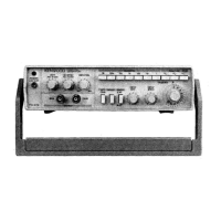
Front Panel Controls:
- POWER Pushbutton (1): Turns the unit on/off, with an LED indicator.
- RANGE (Hz) Selector Switch Assembly (2): Selects one of seven oscillation frequency ranges.
- FUNCTION Selector Switch Assembly (3): Selects output waveform (sine, triangle, or square).
- ATT -20 dB Pushbutton (4): Attenuates the output signal by 20 dB.
- INVERT Pushbutton (5): Inverts the polarity of the output waveform when engaged.
- MAIN/PULSE OUTPUT Jack (6): Outputs the selected waveform (sine, triangle, square) or pulse wave regardless of the FUNCTION switch setting.
- AMPLITUDE Control (7): Varies the amplitude of the output waveform.
- DC OFFSET Control (8): Pulling this knob allows admixing DC voltage with the output signal. Clockwise rotation adds positive voltage, counterclockwise adds negative voltage.
- DUTY/PULL TO VARI (Symmetry Adjustment) Control (9): Controls the symmetry of the output signal. Pulling this knob and rotating it clockwise varies the duty ratio from 1:1 to 5:1, affecting pulse, ramp, saw-tooth, and asymmetric sine waves. Note that this control also changes frequency.
- FREQUENCY Control Dial (10): A variable potentiometer that adjusts the frequency within the range selected by the RANGE switch. Scaled from 0.2 to 2.0.
- SWEEP Selector Pushbutton (11): Engaged for internal sweep, released for external sweep.
- SWEEP RATE Control (12): Controls the sweep rate (sweep frequency) of the internal sweep oscillator.
- SWEEP WIDTH Control (13): Controls the sweep width.
Rear Panel Connectors:
- VCF Input Jack (14): Used for external frequency control. When the SWEEP selector pushbutton is released, applying 0 to 10V to this jack varies the output signal frequency up to a maximum ratio of 100:1.
- Power Connector (15): For AC power supply. Requires the dedicated power cord.
- Fuse Holder (16): Holds the fuse for AC power supply.
Maintenance Features
Fuse Replacement:
If the fuse blows, the cause should be identified and eliminated before replacing it. Use a 0.3 A slow-blow fuse for 100 to 120 V supply voltage, or a 0.2 A fuse for 220 to 240 V supply voltage. The fuse holder is located on the rear panel.
Changing Supply Voltage:
- WARNING: Always disconnect the power cord from the socket before opening the case.
- How to Remove Case: Turn the unit upside down, remove four screws from the case base plate, and then lift the base plate.
- How to Change Supply Voltage: The FG-272 supports supply voltages of 100, 120, 220, and 240 VAC, 50/60 Hz. To change the voltage, remove the case and reconnect the voltage selector plug on the printed circuit board to the desired voltage position on the voltage terminal board.
Precautions:
- Avoid using the FG-272 in direct sunlight, very hot and humid rooms, rooms with excessive mechanical vibrations, or near devices that irradiate strong magnetic forces or pulse voltage.
- While the unit operates immediately upon power-on, allow it to warm up sufficiently after pressing the POWER switch for accurate measurements.
- Do not repeatedly switch the Generator on and off.
- Refer to the "MAINTENANCE" section for instructions on changing the supply voltage.