EasyManua.ls Logo

Kenwood KA-1100D Service Manual

Kenwood KA-1100D
20 pages
To Next Page IconTo Next Page
Page #1 background imageLoading...
Page #1 background image
KA
110
OD
KE
NiV/O1@)
D)
KENWOOD
CORPORATION
SERVICE
MANUAL
C
1986-7
PRINTED
IN
JAPAN
B51-3007-00(B)1154
Panel
ass‘y
Metallic
cabinet
Knob
ass’y
(A20-4963-02)
Knob
ass’y
(A01-1506-01}
(K29-1980-04)
x3
(K29-2486-04)
Knob
Knob
ass'y
(K29-2303-04)
x2
(K29-25
10-04)
{K29-2432-03)
Foot
oe
(JO2-0182-05)
Phone
jack
Knob
ass’y
Phono
jack
Knob
ass‘y
(E11-0162-05)
(K29-2431-04)
x5
(E13-0233-05)
(K29-1980-04)
x2
Knob
Knob
(K29-2305-04)
x2
(K29-2305-04)
x2
Power
cord
bushing
(J42-0083-05)
Phono
jack
(6P)
(E13-0624-05)
x2
AC
outlet*
(F03-0036-05)
AC
outlet’
({f03
-0077-05)
Binding
post
(E21-0006-25)
AC
power
cord”
(BO-}
Phono
jack
(2P)
Phono
jack{6P)
Phono
jack
Screw
terminal
board
(8P)
(E13-0236-05)
(E13-0628-05)
(E13-0235-05)
(£20-0824-05)
*
Refer
to
parts
list
on
page1
B-
Question and Answer IconNeed help?

Do you have a question about the Kenwood KA-1100D and is the answer not in the manual?

Kenwood KA-1100D Specifications

Power IconPower
power output per channel150 watts
maximum continuous power output (DIN)160 W+ 160 W
power consumption260 W
Frequency and Distortion IconFrequency and Distortion
total harmonic distortion0.004%
inter modulation distortion0.003%
frequency response (PHONO ‘RIAA’ Response)20 Hz-20, 000 Hz, +0.2 dB
Signal to Noise Ratio IconSignal to Noise Ratio
PHONO (MM) signal to noise ratio87 dB (2.5 mV)
PHONO (MC) signal to noise ratio76 dB (250 pV)
TUNER/CD/AUX/DAT/TAPE signal to noise ratio110 dB
Input and Output IconInput and Output
PHONO (MM) input sensitivity/impedance2.5 mV/47 kohms, 250 pF
PHONO (MC) input sensitivity/impedance100 xV/100 ohms, 1650 pF
TAPE REC output level/impedance150 mV/220 ohms
Dimensions and Weight IconDimensions and Weight
width440 mm
height170 mm
depth420 mm
weight18 kg

Summary

Front Panel Layout

Component Identification Diagram

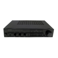
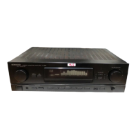
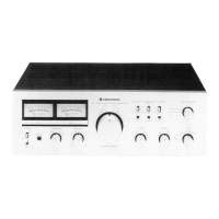
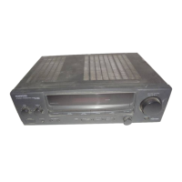
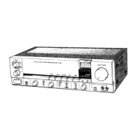
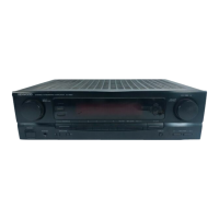
Diagram illustrating external components and their labels.

Disassembly for Repair - Top and Front

Top Cover and Front Panel Removal

Steps for removing the top cover and front panel assembly.

Disassembly for Repair - Bottom Section

Bottom Cover and Jack Removal

Procedures for removing bottom cover and audio jacks.

Block and Level Diagrams

Signal Path Overview

High-level diagram showing signal flow and levels.

Circuit Descriptions

Main and Pre-Amplifier Unit Circuits

Explanations of main and pre-amplifier circuitry.

New VIG DLD Circuit Features

VIG DLD Circuit Principle of Operation

Explanation of the operating principle behind the VIG DLD circuit.

VIG Circuit Effects and Adjustment

VIG Benefits and DLD Check Method

VIG circuit benefits and Super DLD circuit operation check method.

PC Board Layouts

Printed Circuit Board Diagrams

Visual layouts of the unit's printed circuit boards.

Parts List

Component Inventory and Identification

Comprehensive list of part numbers and descriptions.

Schematic Diagrams

Key Circuit Schematics

Schematics for Power, Pre, Tone Amps, and Power Supply.

Specifications

Technical Performance Details

Key technical data including power output and frequency response.

Related product manuals