EasyManua.ls Logo

Kenwood KAF-3010R Service Manual

Kenwood KAF-3010R
17 pages
To Next Page IconTo Next Page
Page #1 background imageLoading...
Page #1 background image
PHONES A SPEAKER B BASS TREBLE BALANCE
INPUT SELECTOR
MUTING LOUDNESS
ON OFF
POWER
ON/STANDBY
MIN MAX
VOLUME CONTROL
MDTAPETUNERPHONOCD
SOURCE DIRECT
thermally reactive advanced instantaneous transistor
T RA I T
L R
ƒ
SL 16 XS-8
+ +
PHONO CD TUNER TAPE
SYSTEM CONTROL
SPEAKERS
AC OUTLETS
UNSWITCHED
100W MAX.
SWITCHED TOTAL
200W MAX.
AC 100V 50/60Hz
A or B : 4–16, A and B : 8–16
REC PLAY REC PLAY
MD
SIGNAL GND
L
R
L R
L R
B
A
AC 220 AC 230
240V
AC 110
120V
STEREO INTEGRATED AMPLIFIER
KAF-1010/3010R
SERVICE MANUAL
© 1998-3/B51-5415-00 (K/K) 1948
Power lens
(B19-1596-08)
Badge
(B43-0302-04)
Power knob*
(K29-)
Speaker knob
(K29-7376-08)
Control knob
(K29-7383-08)
Selector knob
(K29-7379-08)
Push SW
(S68-0105-08)
Phone jack (D6.5)
(E11-0263-08)
Phono jack (2P)
(E11-0188-05)
Slide switch*
(S62-)
Matellic cabinet
(A01-3630-08)
AC power cord bushing
(J42-0200-08)
AC power cord*
(E30-)
Screw terminal board
(E70-0104-08)
AC outlet*
(E03-)
Slide switch
(S62-0069-08)
System jack (D3.5)
(E11-0333-08)
Phono jack (4P)x3
(E63-0186-08)
Front panel
(A60-1492-08)
Function lens
(B19-1592-08)
Volume knob
(K29-7381-08)
Direct lens
(B19-1593-08)
Front frame*
(A22-)
Illustration is KAF-3010R.
* Refer to parts list on page 18.
Loudness lens
(B19-1594-08)
Caution : No connection of ground line if disassemble the unit.
Please connect the ground line on rear panel, PCBs, Chassis and some others.
Remocon window
(B11-0371-08)
KAF-1010(K) 1P 98.4.25 3:57 PM y[W 2
Question and Answer IconNeed help?

Do you have a question about the Kenwood KAF-3010R and is the answer not in the manual?

Kenwood KAF-3010R Specifications

General IconGeneral
BrandKenwood
ModelKAF-3010R
CategoryAmplifier
LanguageEnglish

Summary

CONTROLS

Main Unit Controls

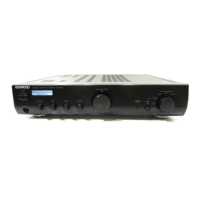
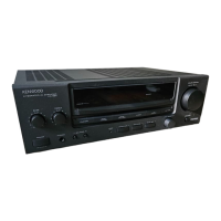
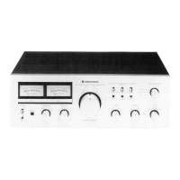
Explains the function and location of each control on the amplifier's front panel.

Remote Control Operation

Details how to use the remote control unit for amplifier functions.

CIRCUIT DESCRIPTION

Microprocessor Pinout

Lists and describes the pins of the TMP87C846N microprocessor.

ADJUSTMENT

Idle Current Setting

Guide for adjusting the unit's idle current, including measurement points.

PCB COMPONENT VIEWS

C Board Component Layout

Shows the component placement on the C printed circuit board.

Main PC Board Component Layout

Shows the component placement on the main printed circuit board.

SCHEMATIC DIAGRAMS

Core Circuit Schematics

Provides schematic diagrams for the main audio circuits.

Power and System Control Schematics

Presents schematic diagrams for power supply and system control sections.

Tone and Volume Control Schematics

Displays schematic diagrams for tone control and volume circuits.

EXPLODED VIEW

Assembly and Parts Identification

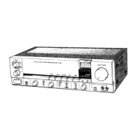
Illustrates the unit's assembly and identifies external parts by number.

PARTS LIST

Component Reference List

Comprehensive list of all parts with their reference, part number, and description.

SPECIFICATIONS

Technical Performance Data

Outlines the technical specifications, including power output and frequency response.

Related product manuals